insulation securely
in
place.
3.
Pull each brush outward from the brush holder
and at the same time insert a stiff piece
of
wire
through the small holes in the base of the holder.
The wire holds the brushes off the slip rings dur-
ing assembly. Install brush block in housing and
tighten mounting screws.
4.
Place the rotor in position for mounting on the
end of the crankshaft and install rotor through-
bolt. Tighten through-bolt just enough to hold
rotor in place.
71
Tightening the rotor through-
ACAUT'oN
bolt
to
specified torque before
the stator assembly is installed can cause rotor
shaft misalignment. Follow recommended ins tal-
lation procedures
to
avoidany possibility ofshaft
misalignment.
5.
Carefully lowerthestator assembly overthe rotor
and into position for assembly to the engine. The
rotor end-bearing should fit snuggly into the
bearing bore hole.
Careless handling
of
the stator
can result in damage
to
the sta-
tor
windings.
Do
not brush the stator windings
against the rotor as it is lowered info position.
6.
Install the four nuts, locking washers, and cap-
screws that secure the stator housing
to
the
engine-to-generator adapter. Tighten capscrews
to specified torque. Note that each locking
washer is installed under capscrew head.
7.
Tighten the rotor through-bolt to the specified
torque.
8. Hold the drip pan
in
position for mounting to the
underside of theset and install the threevibration
isolator center screws. Tighten the rear (genera-
tor end) center screws to the specified torque.
9.
Secure ground strap to drip tray using acapscrew
and two EIT locking washers. Note that ground
strap is installed between locking washers to
insure a good electrical connection.
10. Attach the special lifting plate (see Figure
8-6)
to
the end of the stator housing using four 5/16-18
x
1
capscrews.
11. Attach a hoist or other suitable lifting device to
the lifting plate. Carefully tilt the set back until it is
resting on the drip tray. Remove lifting plate when
complete.
12. Remove the piece of wire that is holding the
brushes off the slip rings. Check the brushes to
verify that they are centered on the slip rings. If
brushes are not centered, loosen the brush block
mounting screws and adjust. Retighten mounting
screws when complete.
13.
Connect the
B+
lead wire to the outboard brush
terminal and the
B-
lead wireto the inboard brush
terminal. Install brush block cover and tighten
cover mounting screws.
14.
Connect the appropriate lead wires to the charge
resistor, low oil pressure cut-off switch, and
igni-
tion coil
B+
terminal.
15.
Place new intake manifold gaskets on the engine
block and install the carburetor and intake mani-
fold assembly. Tighten the intake manifold
screws to the specified torque. Connect the pre-
heater tube, crankcase breather hose, fuel lines,
throttle linkage, and choke heaterwires. Refer to
Fuel System Section 6 for detailed assembly
procedures.
16. Install the noiseshield,flywheel guard, and trans-
former cover.
17. Install the generator set in the vehicle and
securely fasten all mounting screws and hard-
ware. Connect the fuel, exhaust, and electrical
systems in reverse order of disassembly. Refer to
Set Removal Section
5.
18. Fill crankcase with oil of the recommended clas-
sification and viscosity.
BRUSHES
AND
SLIP
RINGS
This section covers brush replacement and slip ring
service.
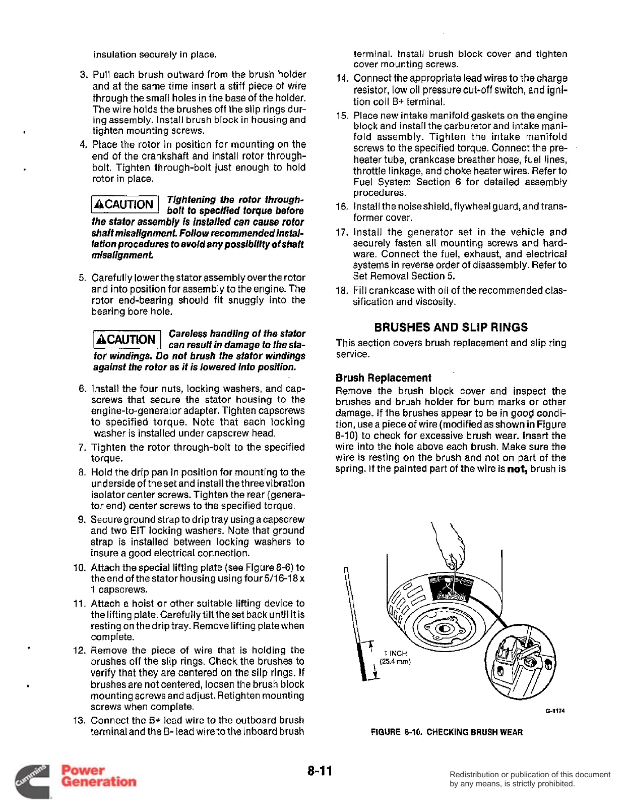
Brush
Replacement
Remove the brush block cover and inspect the
brushes and brush holder for burn marks or other
damage. If the brushes appear to be in good condi-
tion, usea pieceof wire(modifiedasshown in Figure
8-10) to check for excessive brush wear. Insert the
wire into the hole above each brush. Make sure the
wire is resting on the brush and not on part
of
the
spring.
If
the painted part of the wire is
not,
brush is
\a
n
I
G4V4
FIGURE
8-10.
CHECKING
BRUSH
WEAR
8-1
1
Redistribution or publication of this document
by any means, is strictly prohibited.
Redistribution or publication of this document
by any means, is strictly prohibited.
 Loading...


