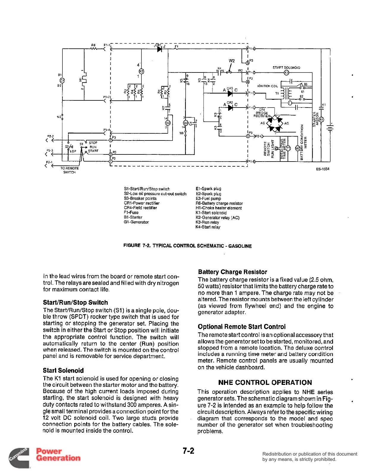
S1-Start/Run/Stop switch
SZ-Low
oil
pressure cut-out switch
S3-Breaker points
CR1-Power rectifier
CR6Field rectifier
F1-Fuse
B1-Starter
G1-Generator
El-Spark plug
EZ-Spark plug
E3-Fuel pump
R6-Battery charge resistor
H1-Choke heater element
K1-Start solenoid
KZ-Generator relay (AC)
K3-Run relay
K4-Start relay
FIGURE
7-2.
TYPICAL CONTROL SCHEMATIC
-
GASOLINE
in the lead wires from the board or remote start con-
trol.The relays are sealed and filled with dry nitrogen
for maximum contact life.
Start/Run/Stop Switch
The Start/Run/Stop switch
(Sl)
is a single pole, dou-
ble throw (SPDT) rocker type switch that is used for
starting or stopping the generator set. Placing the
switch in either the Start
or
Stop position will initiate
the appropriate control function. The switch will
automatically return to the center (Run) position
when released. The switch is mounted on the control
panel and is removable for service department.
Start Solenoid
The
K1
start solenoid is used for opening or closing
the circuit between the starter motor and the battery.
Because of the high current loads imposed during
starting, the start solenoid
is
designed with heavy
duty contacts rated to withstand
300
amperes.
A
sin-
gle small terminal providesaconnection pointforthe
12
volt DC solenoid coil. Two large studs provide
connection points for the battery cables. The sole-
noid is mounted inside the control.
Battery Charge Resistor
The battery charge resistor is a fixed value
(2.5
ohm,
50
watts) resistorthat limits the batterycharge rate to
no more than
1
ampere. The charge rate may not be
-
altered. The resistor mounts between the left cylinder
(as viewed from flywheel end) and the engine to
generator adapter.
Optional Remote Start Control
The remote start control is an optional accessory that
allows the generator set to be started, monitored, and
stopped from a remote location. The deluxe control
includes a running time meter and battery condition
meter. Remote control panels are usually mounted
on the vehicle dashboard.
NHE CONTROL OPERATION
This operation description applies to
NHE
series
generator sets. The schematic diagram shown in Fig-
ure
7-2
is intended as an example to help follow the
circuit description. Always refer to the specific wiring
diagram that corresponds to the model and spec
number
of
the generator set when troubleshooting
problems.
7-2
Redistribution or publication of this document
by any means, is strictly prohibited.
Redistribution or publication of this document
by any means, is strictly prohibited.
 Loading...


