TABLE
8-2
RESISTANCE VALUES FOR ROTORS
KW
6.5
STACK LENGTH RESISTANCE*
4.72 in. (120 mm) 10.6 ohm (+lo%)
*At 77"
F
(25"
C)
To test for shorted windings, set the ohmmeter for the
lowest scale. Place the test prods on the slip rings as
shown in Figure 8-12.
A
reading less than the value
shown in Table 8-2 indicates shorted windings.
Replace a rotor with shorted windings with a new rotor.
n
ES-1559
FIGURE
8-13
TESTING
ROTOR
FOR
OPENS
OR
SHORTS
Stator/Transformer Test
The stator and transformer can be tested for
grounded or open windings using an ohmmeter.
Testing for shorted windings requires a digital-type
ohmmeter than can read to within
0.01
ohms.
Figures 8-14 and 8-15 show the stator and trans-
former removed from the generator for testing. How-
ever, it is possible to test both components without
removing them from the generator. Remove the con-
trol panel and transformer cover to obtain access to
the specified lead wires during testing.
Ground
Tesf:
To test for grounds, disconnect the
following transformer and stator leads.
Stator lead
S1
from tap
X2
Stator lead TI from CB1
Stator lead T3 from CB2
:
Stator lead
S2
from CR4-AC1
0
Stator lead B1 from R6-1/H1-1 lead
0
Stator lead
B2
from ground tab
0
Transformer lead
H1
from ground
0
Transformer lead H3 from ground
0
CR4-AC2
lead wire from tap
X5
wire
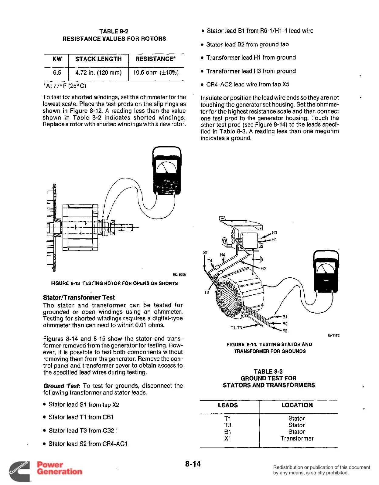
Insulate or position the lead wire ends
so
they are not
touching the generator set housing. Set the ohmme-
ter for the highest resistance scale and then connect
one test prod to the generator housing. Touch the
other test prod (see Figure 8-14) to the leads speci-
fied in Table
8-3.
A reading less than one megohm
indicates a ground.
?
H4
@!!!:
FIGURE
8-14.
TESTING STATOR AND
TRANSFORMER
FOR
GROUNDS
TABLE
8-3
GROUND TEST
FOR
STATORS AND TRANSFORMERS
LEADS LOCATION
Stator
Stator
Stator
Transformer
I
8-1
4
Redistribution or publication of this document
by any means, is strictly prohibited.
Redistribution or publication of this document
by any means, is strictly prohibited.
 Loading...


