CHOKE PULL-OFF
n
AIR~PREHEATER
db-1
\\\
\
91
i
INTAKE MANIFOLD
\\
FUEL LINE
\,a
‘1
GOVERNOR CONTROL LINKAGE
FS-1607
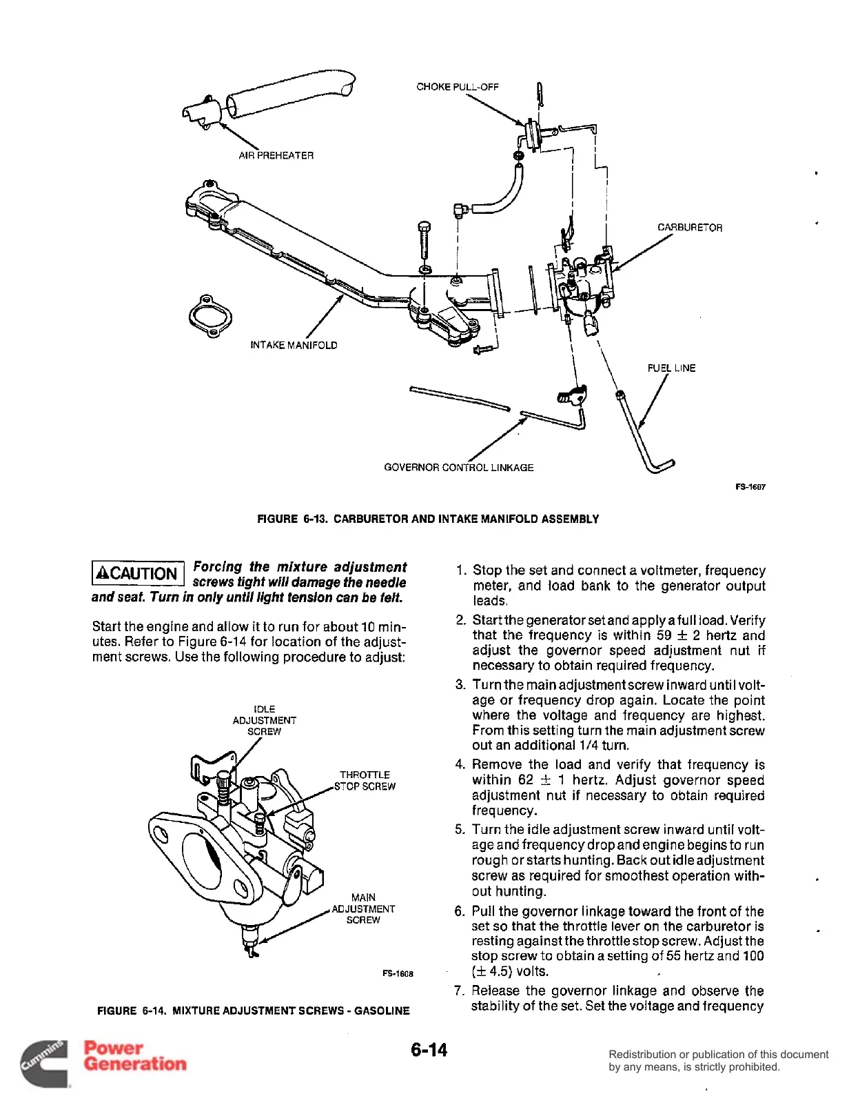
FIGURE 6-13.
CARBURETOR
AND
INTAKE
MANIFOLD
ASSEMBLY
Forcing the mixture adjustment
@%&%I
screws fight
wi//
damage the needle
and seat. Turn in only
until
light tension can be felt.
1.
Stop the set and connect a voltmeter, frequency
meter, and load bank to the generator output
leads.
2.
Start the generator set and applyafull load. Verify
that the frequency
is
within
59
k
2
hertz and
adjust the governor speed adjustment nut if
necessary to obtain required frequency.
Start the engine and allow it to run for about 10 min-
Utes. Refer to Figure 6-14 for location of the adjust-
ment screws. Use the following procedure to adjust:
3.
Turn the main adjustment screw inward until volt-
age or frequency drop again. Locate the point
where the voltage and frequency are highest.
From this setting turn the main adjustment screw
out an additional 1/4 turn.
4. Remove the load and verify that frequency is
within
62
k
1
hertz. Adjust governor speed
adjustment nut if necessary to obtain required
frequency.
5.
Turn the idle adjustment screw inward until volt-
age and frequency dropand engine begins to run
rough or starts hunting. Back out idle adjustment
screw as required for smoothest operation with-
6.
Pull the governor linkage toward the front of the
set
so
that the throttle lever on the carburetor is
resting against the throttle stop screw. Adjust the
stop screw to obtain a setting
of
55
hertz and 100
7.
Release the governor linkage and observe the
stability
of
the set. Set the voltage and frequency
IDLE
ADJUSTMENT
SCREW
THROTTLE
STOP
SCREW
MAIN
out hunting.
ADJUSTMENT
SCREW
FS-1608
(k
4.5) volts.
FIGURE
6-14.
MIXTURE
ADJUSTMENT
SCREWS
-
GASOLINE
6-1
4
Redistribution or publication of this document
by any means, is strictly prohibited.
Redistribution or publication of this document
by any means, is strictly prohibited.
 Loading...


