,
VOLTAGE
ADJUSTMENT
To Increase
Voltage
TRANSFORMER VOLTAGE
ADJUSTMENTS
The
generator output voltage may
be
adjusted
by
changing the connections to the transformer secondary
taps. This is necessary if the set voltage falls outside the
recommended voltage range when operating at the
specified frequency. Use the following procedures to
adjust the generator output voltage:
CR4-AC
s1
TO TO
x3
x4
x2
x4
xi
x4
x3
x5
1.
Adjust the governor as specified
in
the Governor
section before making adjustments to the trans-
former.
2.
Check the generator voltage with the warmed-up-
set operating at no load and
62
hertzfrequency. The
nominal voltage should be
127.5
f
4.5
volts
AC.
3.
Stop the set and adjust the transformer tap connec-
tions as shown in Table
8-1
to increase or decrease
the voltage as required.
4.
Repeat the voltage check and continue to make
adjustments until voltage is within range specified.
5.
Check the no load and full load voltage and fre-
quency as specified under Governor in Section
6.
Voltage and frequency should stay within the limits
shown in Table
8-1.
Start the generator set and allow
it
to stabilize. Measure
the field voltage with no load applied and then with full
load applied. Both readings should fall within a range of
18
to
60
volts
DC. Remove
test
leads
and
replace
brush
block cover when test is complete.
Rotor
Test
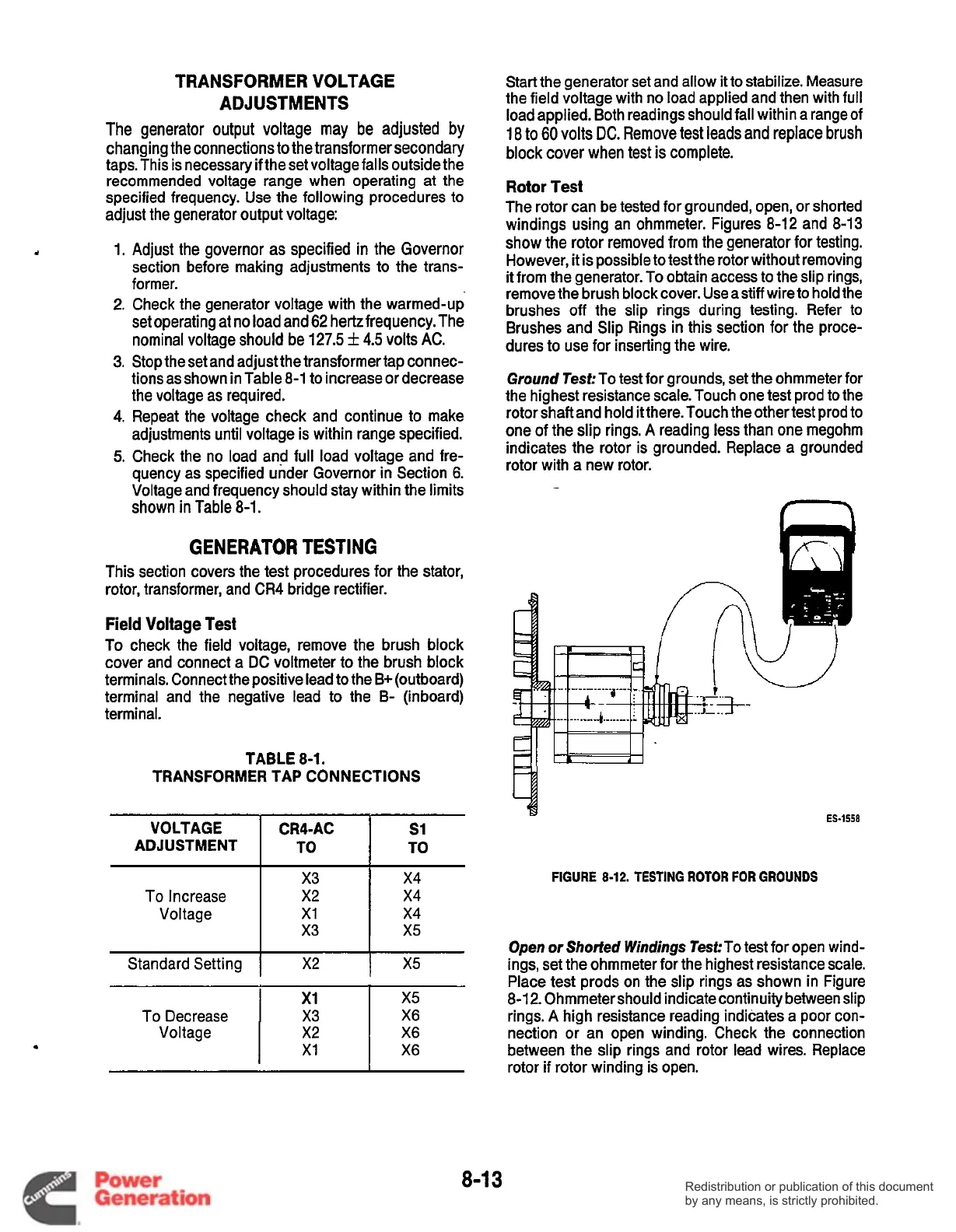
The rotor can be tested for grounded, open, or shorted
windings using an ohmmeter. Figures
8-12
and
8-13
show the rotor removed from the generator for testing.
However, it is possible to test the rotor without removing
it
from the generator.
To
obtain access to the slip rings,
remove the brush block cover. Use astiff wire to hold the
brushes
off
the slip rings during testing. Refer to
Brushes and Slip Rings in this section for the proce-
dures to use for inserting the wire.
Ground
Test: To test for grounds, set the ohmmeter for
the highest resistance scale. Touch one test prod to the
rotor shaft and hold
it
there. Touch the other test prod to
one of the slip rings.
A
reading less than one megohm
indicates the rotor is grounded. Replace a grounded
rotor with a new rotor.
.
GENERATOR
TESTING
This section covers the test procedures for the stator,
rotor, transformer, and CR4 bridge rectifier.
Field
Voltage
Test
To check the field voltage, remove the brush block
cover and connect a
DC
voltmeter to the brush block
terminals. Connect the positive lead to the
B+
(outboard)
terminal and the negative lead to the
B-
(inboard)
terminal.
TABLE
8-1.
TRANSFORMER TAP CONNECTIONS
Standard Setting
I
X2
1
X5
x1
To Decrease
I
x3
I
E
Voltage
x5
X6
X6
X6
ES-1558
FIGURE
8-12.
TESTING
ROTOR
FOR GROUNDS
Open
or
Shorted Windings
TeskTo test for open wind-
ings, set the ohmmeter for the highest resistance scale.
Place test prods on the slip rings as shown in Figure
8-1
2.
Ohmmeter should indicate continuity between slip
rings.
A
high resistance reading indicates a poor con-
nection or an open winding. Check the connection
between the slip rings and rotor lead wires. Replace
rotor if rotor winding is open.
8-1
3
Redistribution or publication of this document
by any means, is strictly prohibited.
Redistribution or publication of this document
by any means, is strictly prohibited.
 Loading...


