PISTON
ASSEMBLY
The piston assembly consists of the piston, piston
rings, piston pin, connecting rod assembly, and bear-
ing. After removal from the engine, all parts must be
carefully inspected for damage and wear before
replacing.
Removal and Disassembly
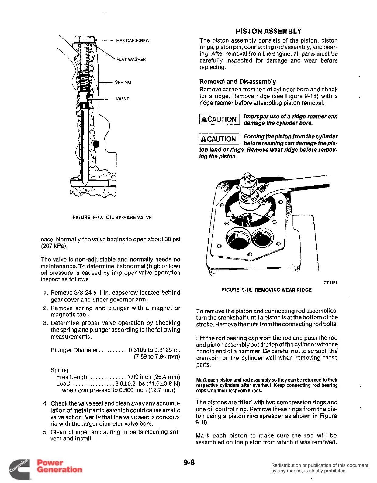
Remove carbon from top of cylinder bore and check
for a ridge. Remove ridge (see Figure
9-18)
with a
ridge reamer before attempting piston removal.
Improper
use
of a ridge reamer can
damage
fhe
cylinder bore.
1-1
Forcing the piston from
fhe
cylinder
before reaming can damage fhe pis-
ton land or rings. Remove wear ridge before remov-
ing the piston.
HEX
CAPSCREW
FLAT
WASHER
FIGURE
9-17.
OIL BY-PASS VALVE
CT-1058
case. Normally the valve begins to open about 30 psi
(207
kPa).
The valve is non-adjustable and normally needs
no
maintenance.To determine if abnormal (high or low)
oil pressure is caused by improper valve operation
inspect as follows:
1.
2.
3.
4.
5.
Remove
3/8-24
x
1
in. capscrew located behind
gear cover and under governor arm.
Remove spring and plunger with a magnet or
magnetic tool.
Determine proper valve operation
by
checking
thespring and plungeraccording to the following
measurements.
Plunger Diameter..
,
.
.
.
.
.
.
.
0.3105 to 0.3125 in.
(7.89 to
7.94
mm)
Spring
Free Length.,
. .
.
.
. . .
.
.
.
.
1.00
inch (25.4 mm)
Load
.
,
.
.
,
.
.. .
..
.
. .
.2.6-+0.2 Ibs
(11.6f0.9
N)
when compressed to
0.500
inch (12.7 mm)
Check the valveseat and clean away anyaccumu-
lation of metal particles which could causeerratic
valve action. Verify that the valve seat is concent-
ric with the larger diameter valve bore.
Clean plunger and spring in parts cleaning sol-
vent and install.
FIGURE
9-18.
REMOVING WEAR RIDGE
To
remove the piston and connecting rod assemblies,
turn the crankshaft until a piston is at the bottom of the
stroke. Remove the nuts from theconnecting rod bolts.
Lift the rod bearing cap from the rod and push the rod
and piston assembly out the top of the cylinder with the
handle end of a hammer. Be careful not to scratch the
crankpin or the cylinder wall when removing these
parts.
Mark each piston and rod assembly
so
they can be returned to their
respective cylinders after overhaul. Keep connecting rod bearing
caps with their respective rods.
The pistons are fitted with two compression rings and
one oil control ring. Remove these rings from the pis-
ton using a piston ring spreader as shown in Figure
9-1
9.
.
Mark each piston
to
make sure the rod will be
assembled on the piston from which it was removed.
9-8
Redistribution or publication of this document
by any means, is strictly prohibited.
Redistribution or publication of this document
by any means, is strictly prohibited.
 Loading...


