1.
Slide in throttle shaft and install throttle plate
using new screws, if furnished in repair kit. Before
tightening the screws, the plate must be centered
in the bore.
To
do
so,
back off the throttle stop
screw as necessary and completely close the
throttle lever. Seat the plate by gently tapping
with a small screwdriver, then tighten screws.
Install the choke shaft and plate in the same
manner.
FS-1483
FIGURE 6-16.
MIXTURE
NEEDLE INSPECTION
-
GASOLINE
Install idle mixture screw assembly. Turn in screw
until lightly seated and then out the number of
turns specified in Table 6-2.
Forcing the mixture adjustmenf
screws tight will damage the
needle and seat Turn in only untillight tension
is
felt.
Install needle valveand seat, fuel bowl gasket and
float assembly. Make sure that all clips and
springs are properly placed and that the float
moves freely without binding. See Figure 6-17.
POSITION
HOOK
NDER TANG ON
FS-1610
POSITION OF SPRING
,AL
AFTER INSTALLATION
FIGURE 6-17. FLOAT INSTALLATION
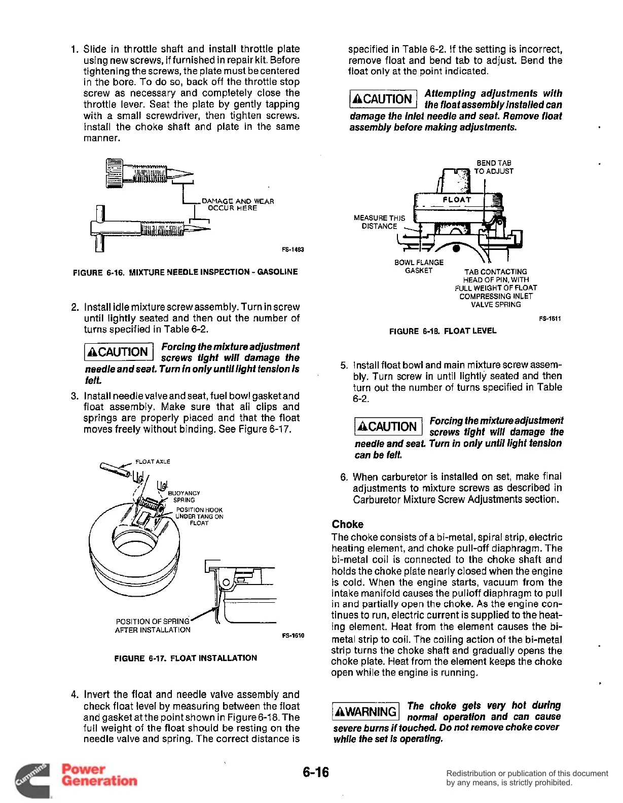
Invert the float and needle valve assembly and
check float level by measuring between the float
and gasket at the point shown in Figure 6-18.The
full weight of the float should be resting on the
needle valve and spring. The correct distance is
specified in Table 6-2. If the setting is incorrect,
remove float and bend tab to adjust. Bend the
float only at the point indicated.
Attempting adjustments with
k&%!!@l
the
floaf
assembly installed can
damage the inlet need/e and seat. Remove float
assembly before making adjustments.
BEND TAB
*I+--
BOWL FLANGE
\L
'
TAB CONTACTING
HEAD
OF
PIN, WITH
FULL WEIGHT OF FLOAT
COMPRESSING INLET
VALVE SPRING
GASKET
FS-1611
FIGURE 6-18. FLOAT LEVEL
Install float bowl and main mixture screw assem-
bly. Turn screw in until lightly seated and then
turn out the number of turns specified in Table
6-2.
Forcing the mixture adjustmefit
screws tight will damage the
needle and seat. Turn in only until light tension
can be felt.
When carburetor is installed on set, make final
adjustments to mixture screws as described in
Carburetor Mixture Screw Adjustments section.
Choke
The choke consists of a bi-metal, spiral strip, electric
heating element, and choke pull-off diaphragm. The
bi-metal coil is connected to the choke shaft and
holds the choke plate nearly closed when the engine
is cold. When the engine starts, vacuum from the
intake manifold causes the pulloff diaphragm to pull
in and partially open the choke.
As
the engine con-
tinues to run, electric current is supplied to the heat-
ing element. Heat from the element causes the bi-
metal strip to coil. The coiling action of the bi-metal
strip turns the choke shaft and gradually opens the
choke plate. Heat from the element keeps the choke
open while the engine is running.
t
The choke gets
very
hot during
normal operation and can cause
severe burns if touched.
Do
nof remove choke cover
while fhe set is operating.
6-1
6
Redistribution or publication of this document
by any means, is strictly prohibited.
Redistribution or publication of this document
by any means, is strictly prohibited.
 Loading...


