\
-
THIN
SIDEOFCAP
MARKS-ROD#2
-
1
-
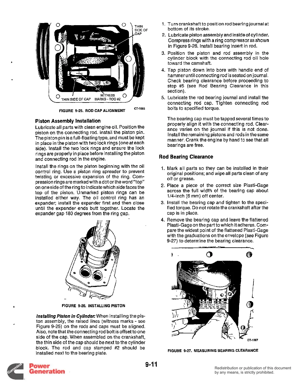
FIGURE
9-25.
ROD
CAP ALIGNMENT
cT-1065
Piston
Assembly
Installation
Lubricate all parts with clean engine oil. Position the
piston on the connecting rod. Install the piston pin.
The piston pin isa full-floating type, and must be kept
in place in the piston with two lock rings (one at each
side). Install the two lock rings and ensure the lock
rings are properly in place before installing the piston
and connecting rod in the engine.
Install the rings on the piston beginning with the oil
control ring. Use a piston ring spreader to prevent
twisting or excessive expansion of the ring. Com-
pression rings are marked with a dot or the word “top”
on oneside of the ring to indicate which side faces the
top of the piston. Unmarked piston rings can be
installed either way. The oil control ring has an
expander: install the expander first and then close
until the expander ends butt together. Locate the
expander gap
180
degrees from the ring gap.
FIGURE
9-26.
INSTALLING
PISTON
lnsfalling
Piston
in
Cy/indec
When installing the pis-
ton assembly, the raised lines (witness marks
-
see
Figure 9-25) on the rods and caps must be aligned.
Also,
note that the connecting rod bolt is offset to one
side of the cap. When assembled on the crankshaft,
the thin side of the cap should be next to the cylinder
block. The rod and cap stamped #2 should be
installed next to the bearing plate.
1.
Turn
crankshaft to position
rod
bearing journal
at
bottom of its stroke.
2.
Lubricate piston assembly and inside of cylinder.
Compress rings with
a
ring compressor
as
shown
in
Figure
9-26.
install bearing insert in rod.
3.
Position the piston and rod assembly in the
cylinder block with the connecting rod oil hole
toward the camshaft.
4.
Tap piston down into bore with handle end of
hammer until connecting rod isseated on journal.
Check bearing clearance before proceeding to
step
#5
(see Rod Bearing Clearance in this
section).
5.
Lubricate the rod bearing journal and install the
connecting rod cap. Tighten connecting
rod
bolts to specified torque.
The bearing cap must be tapped several times to
properly align
it
with the connecting rod. Clear-
ance varies on the journal if this is not done.
Install the remaining pistonsand rods in thesame
manner. Crank the engine by hand to see that all
bearings are free.
Rod
Bearing Clearance
1.
Mark all parts
so
they can be installed in their
original positions; and wipe all parts clean of any
oil or grease.
2. Place a piece of the correct size Plasti-Gage
across the full width of the bearing cap about
1/4-inch
(6
mm) off center.
3.
Install the bearing cap and tighten to the speci-
fied torque.
Do
not rotate the crankshaft after the
cap is in place.
4.
Remove the bearing cap and leave the flattened
Plasti-Gage on the partto which it adheres.
Com-
pare the widest point of the flattened Plasti-Gage
with the graduations on the envelope (see Figure
9-27) to determine the bearing clearance.
‘X-
3’
0
@
FIGURE
9-27.
MEASURING BEARING CLEARANCE
9-1
1
Redistribution or publication of this document
by any means, is strictly prohibited.
Redistribution or publication of this document
by any means, is strictly prohibited.
 Loading...


