5.15
BODY / STEERING / SUSPENSION
5
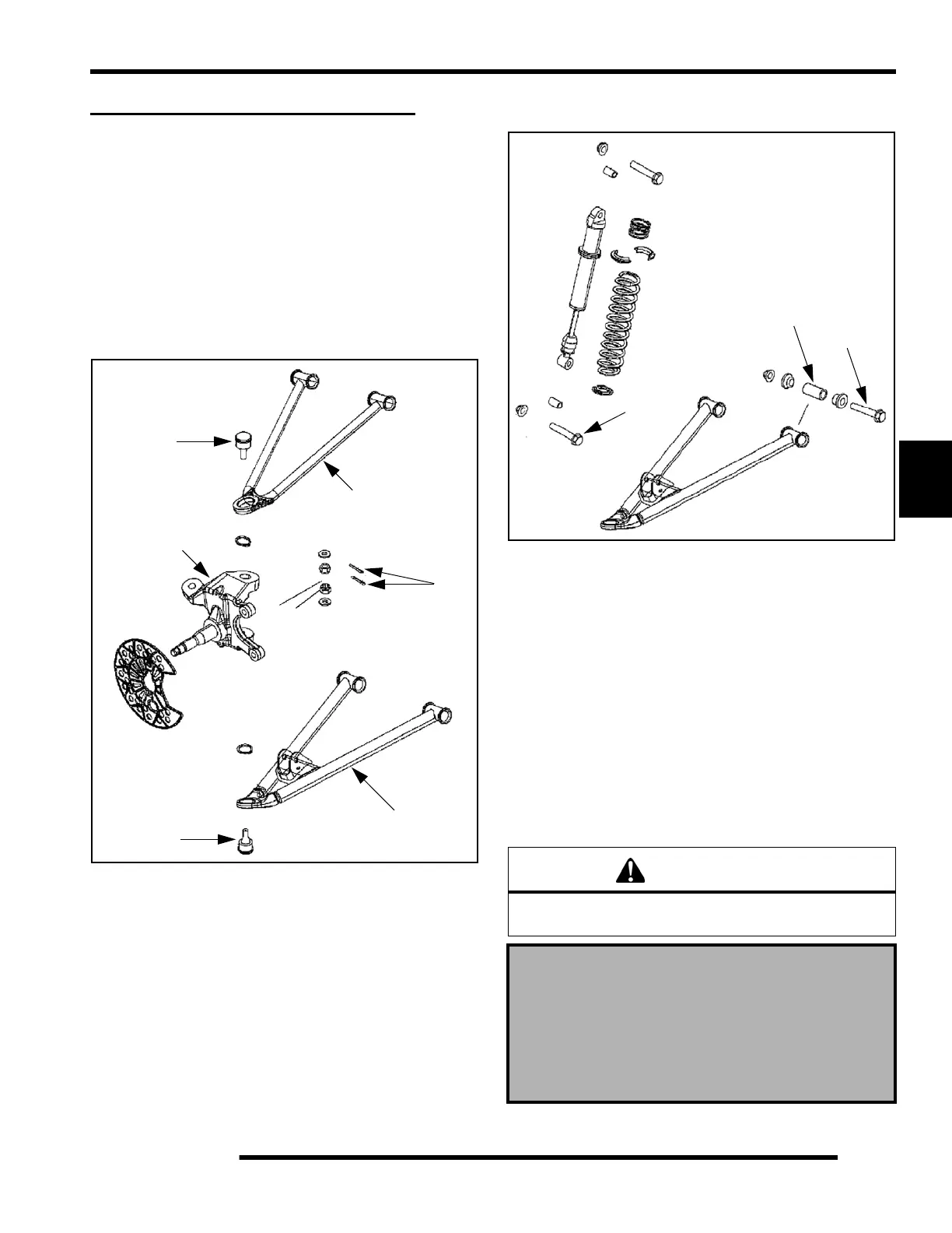
FRONT A-ARM REPLACEMENT
A-arm Removal and Inspection
1. Elevate and safely support vehicle. Remove the front
wheel(s).
2. Remove the upper and lower ball joint cotter pins (A) from
the ball joint studs (B & C) at wheel end of A–arm. Remove
the ball joint nuts until the nuts are flush with end of the ball
joints studs.
3. Push up on the upper A-arm (D) to remove the A-arm from
the steering knuckle (E). Push down on the lower A-arm (F)
to remove the A-arm from the steering knuckle (E).
4. Remove the lower shock bolt (G) from the lower A-arm and
remove the shock from the A-arm.
5. Loosen two bolts on the A–arm tubes (H) (upper and lower
A-arms) until A–arm can be removed.
6. Examine A–arm shafts (I). Replace if worn. Discard
hardware.
A-arm Installation
1. Insert A–arm shaft (I) into the new A–arm (D & F).
2. Install new A–arm assembly onto vehicle frame (upper and
lower). Torque bolts to 33 ft. lbs. (45 Nm).
3. Attach upper A-arm (D) and lower A–arm (F) to steering
knuckle (E). Attach shock with bolts (G). Tighten all
fasteners to 33 ft. lbs. (45 Nm). If ball joint cotter pin holes
are not aligned, tighten nut slightly to align. Install a new
cotter pin with open ends toward rear of machine (upper and
lower). Bend ends in opposite directions around nut.
4. Locate grease fittings at the end of each A–arm tube and
pump A–arm ends full of grease.
A
B
C
D
E
F
WARNING
Upon A–arm installation completion, test vehicle at low
speeds before putting into regular service.
A-arm Attaching Bolt Torque:
Ball Joint Stud Nut Torque:
Front Shock Bolt Torque:
33 ft. lbs. (45 Nm)
G
H
I
 Loading...