5.18
BODY / STEERING / SUSPENSION
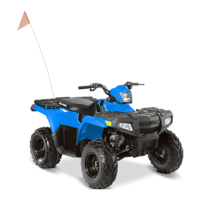
2. Disassemble, clean and inspect the lower A-arm thrust
washers, needle bearing, seals and shaft. Replace
components as required.
3. Inspect needle bearing performance by rotating the shaft
inside the bearing (circled). If replacement is required,
press the bearings out from opposite sides using a drift
punch or other suitable tool.
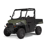
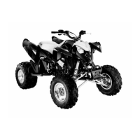
4. Press needle bearings (A) from the A-arms using a drift
punch or other suitable tool. Do not re-use bearings once
they have been removed.
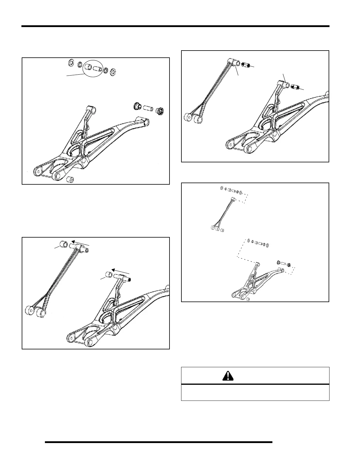
5. Press new needle bearings (A) into the A-arms, centering
bearing in the bore. Press only on the outside diameter of
the bearing. Verify that an equal amount of space remains
on each side to allow for seal installation.
NOTE: Apply grease to the inside of the needle
bearings before inserting shaft.
6. Insert A–arm shafts, seals and thrust washers into the A–
arm mounting bores.
A-arm Installation
1. Install A–arm assemblies onto vehicle frame (upper and
lower). Torque bolts to 33 ft. lbs. (45 Nm).
2. Attach upper A-arm and lower A–arm to hub carrier. (E).
Tighten both fasteners to 33 ft. lbs. (45 Nm).
3. Locate grease fittings at the upper and lower A-arm
bushings and pump full of grease.
Inspect
A
A
WARNING
Upon A–arm installation completion, test vehicle at low
speeds before putting into regular service.
A
A
 Loading...