3.22
ENGINE
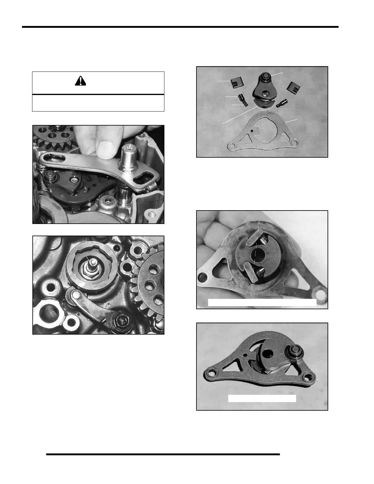
Shifter Component Removal and Inspection
1. With the clutch basket removed, remove the shift shaft
assembly (A), guide plate (D), pawl assembly (B), and
stopper arm / detent spring assembly (C).
2. Remove the shift cam by loosening the shifter pin bolt (E).
3. Inspect the ratcher pawls (F), pawl plungers (G), plunger
springs (H), shifter collar (J), shifter drum (K) and guide
plate (L) for wear or damage. Replace if wear or damage
is evident.
4. Installation: Reverse the procedures, paying close attention
to the orientation of the ratcher pawls (F) during
installation, as the surface must be flat when the pawls are
installed correctly. The guide plat (L) should be installed
with the “dot” facing upward. Torque the guide plate bolts,
the detent spring assembly bolt and the shifter pin bolt (E)
to 80–97 in. lbs. (9–11 Nm).
CAUTION
Stopper arm (C) is under spring pressure.
Use care during removal.
A
B
C
D
E
F
G
H
J
K
L
L
Correct for installation - Flat Surface
Correct for installation

 Loading...