Qty Value Description Component numbers
1 Rotary encoder with shaft button SW1
1 1602 HD44780 LCD 1602, yellow/green back-light
1 20MHz HC49/4H quartz crystal XTAL1
1 27MHz HC49/4H quartz crystal XTAL2
1 PCB Main PCB
1 PCB Display PCB panel
2 Knob Knob to fit rotary encoder and R36
1 200cm 0.33mm diameter wire (AWG #28)
1 M3 10mm Steel 10mm long M3 screw
1 M3 Steel M3 nut
1 M3 12mm Steel 12mm diameter M3 washer
5 11mm Nylon M3 hex spacer
10 6mm Nylon M3 6mm screw
2 6mm Nylon or steel M3 6mm screw
2 Nylon or steel M3 nut
3. Assembly – general guidelines
Assembly of this kit is quite straightforward. But there are quite a lot of components. So
please keep them methodically in trays or some convenient storage boxes, and be careful
not to misplace any. The usual kit-building recommendations apply: work in a well-lit area,
with peace and quiet to concentrate. The IC (chips) and some of the other
semiconductors in the kit are sensitive to static discharge. Therefore, observe
Electrostatic discharge (ESD) precautions. And I say
it again: FOLLOW THE INSTRUCTIONS!! Don’t try to
be a hero and do it without instructions!
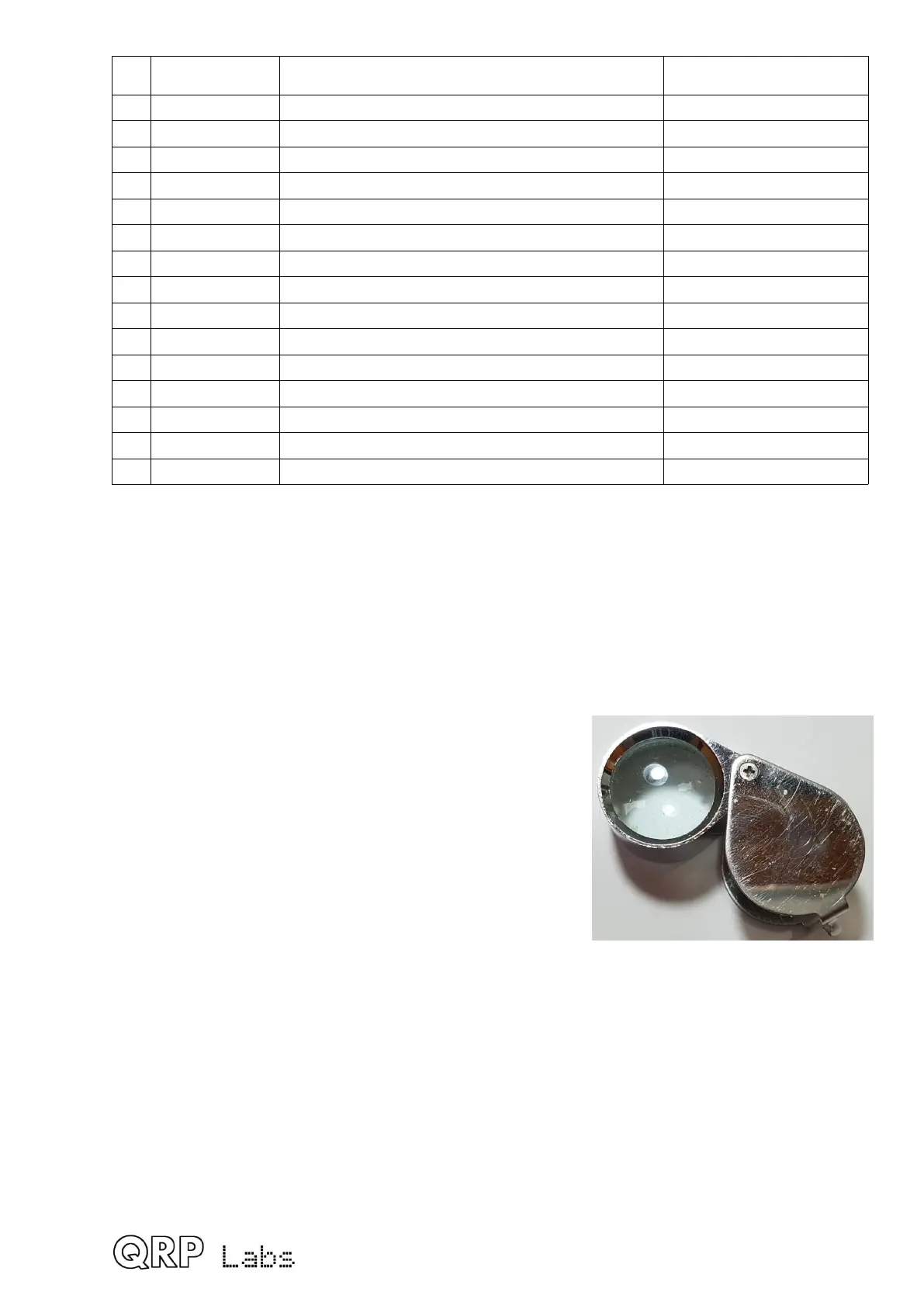
A jeweler's loupe is really useful for inspecting small
components and soldered joints. You’ll need a fine-
tipped soldering iron too. It is good to get into the habit
of inspecting every joint with the magnifying glass or
jeweler's loupe (like this one I use), right after soldering.
This way you can easily identify any dry joints or solder
bridges, before they become a problem later on when
you are trying to test the project.
You could also take photos with a mobile phone, and use the phone’s zoom features to
view the board in detail.
Triple check every component value and location BEFORE soldering the component!
It is easy to put component leads into the wrong holes, so check, check and check again! It
is difficult to de-solder and replace components, so it is much better to get them correctly
installed the first time. In the event of a mistake, it is always best to detect and correct any
errors as early as possible (immediately after soldering the incorrect component). Again, a
reminder: removing a component and re-installing it later is often very difficult!
Please refer to the layout diagram and PCB tracks diagrams below, and follow the steps
very carefully.
10
 Loading...
