We hope you enjoy building and operating this kit! Please read this assembly manual
carefully, and follow the instructions step by step in the recommended order. Later in the
manual the circuit design is described in detail and we recommend reading and
understanding this section too, to get the maximum enjoyment and education from your
new radio.
Typical performance measurements are shown in the measurements section. The
operation section of the manual describes transceiver, alignment and test equipment
operation in detail.
There is a single page reference “cheat sheet” near the end of the manual.
Please check the QCX-mini web page :B$JEEH$EH> for any updates tips,
etc., before starting the assembly.
Please make use of troubleshooting resources at :B$JEEH$EH> if you have
any problems. If you need further help, join the QRP Labs discussion forum on
groups.io and post a message about your problem.
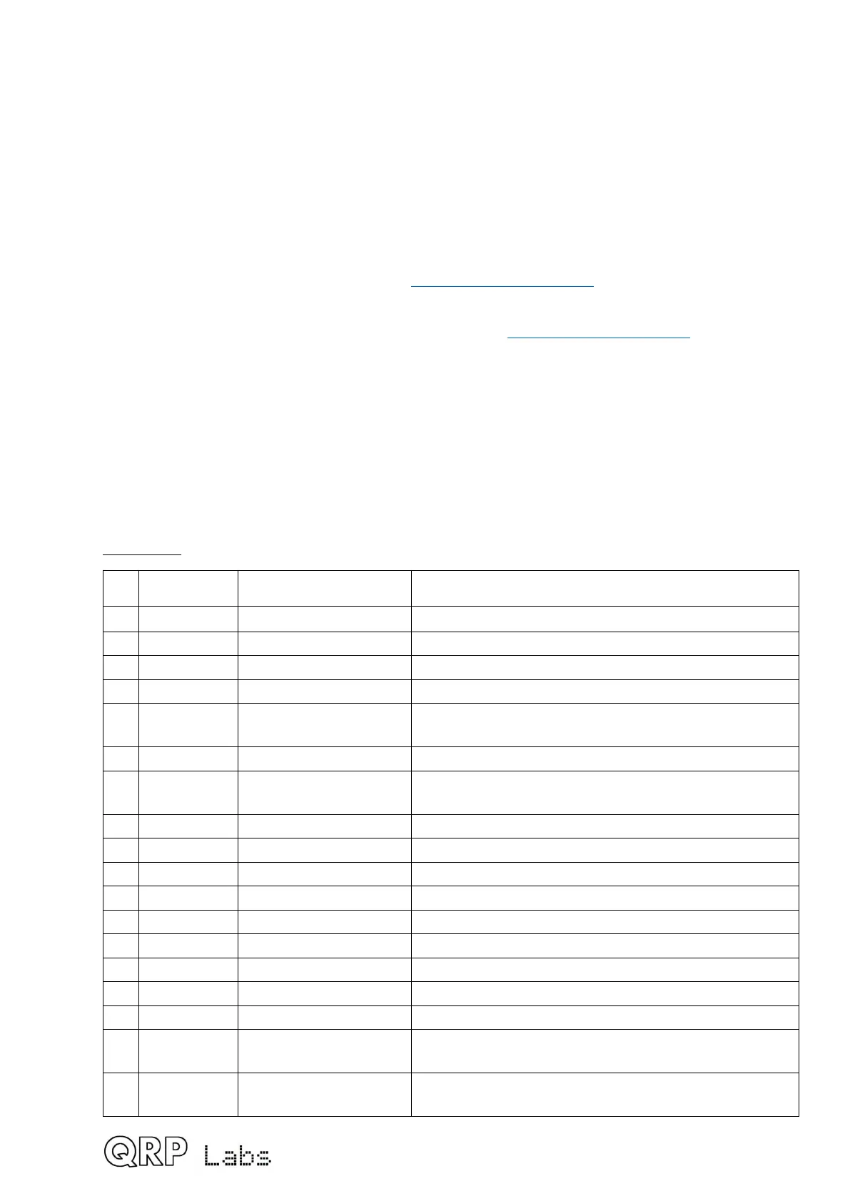
2. Parts list
Many components are SMD, pre-soldered to the PCB in the factory. Only through-hole
components need to be installed by the constructor. SMD components in the parts list are
identified in the Description column and by the text colour being purple.
Resistors
Qty Value Description Component numbers
4 100-ohms SMD R5, 6, 8, 9
1 150-ohms SMD R41
1 270-ohms SMD R50
1 560-ohms SMD R48 (on display board)
11 1K SMD R3, 4, 19, 26, 37, 45, 49, 54, 55, 62, 63
(R45 on display board)
1 1.2K SMD R42
13 3.3K SMD R12, 13, 15, 16, 20, 22, 23, 25, 44, 53, 56, 59, 65
(R44 on controls board, R65 on display board)
1 3.9K SMD R61
1 4.3K SMD R18
1 5.1K SMD R11
16 10K SMD R1,2,7,10,14,21,34,36,39,40,46,51,52,57,58,64
2 33K SMD R28, 29
2 36K SMD R32, 33
2 47K SMD R30, 31
4 120K SMD R38, 43, 60, 100 (R100 on display board)
1 750K SMD R35
1 500-ohm Multi-turn trimmer
potentiometer
R27
2 50K Multi-turn trimmer
potentiometer
R17, 24
5
 Loading...
