EasyManuals Logo
Home>QRP Labs>Transceiver>QCX-mini

QRP Labs QCX-mini Assembly Instructions

Default Icon
121 pages
To Next Page IconTo Next Page
To Previous Page IconTo Previous Page
Page #66 background imageLoading...
Page #66 background image
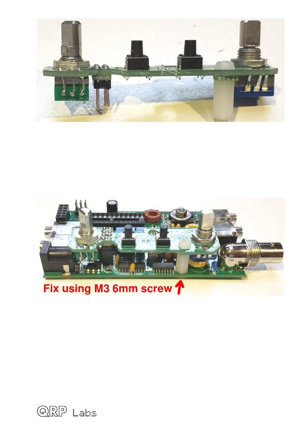
3.40 Fit Controls PCB to main PCB
Now fit the Controls PCB to the main PCB by plugging together the two 2x4-pin header
connectors.
Fit an M3 6mm screw from the underside of the main PCB, screwed into the 11mm nylon
hex spacer pillar that is fixed to the Controls PCB, as shown in the following photograph.
 66

Table of Contents

Other manuals for QRP Labs QCX-mini

Questions and Answers:

Question and Answer IconNeed help?

Do you have a question about the QRP Labs QCX-mini and is the answer not in the manual?

QRP Labs QCX-mini Specifications

General IconGeneral
BrandQRP Labs
ModelQCX-mini
CategoryTransceiver
LanguageEnglish

Related product manuals