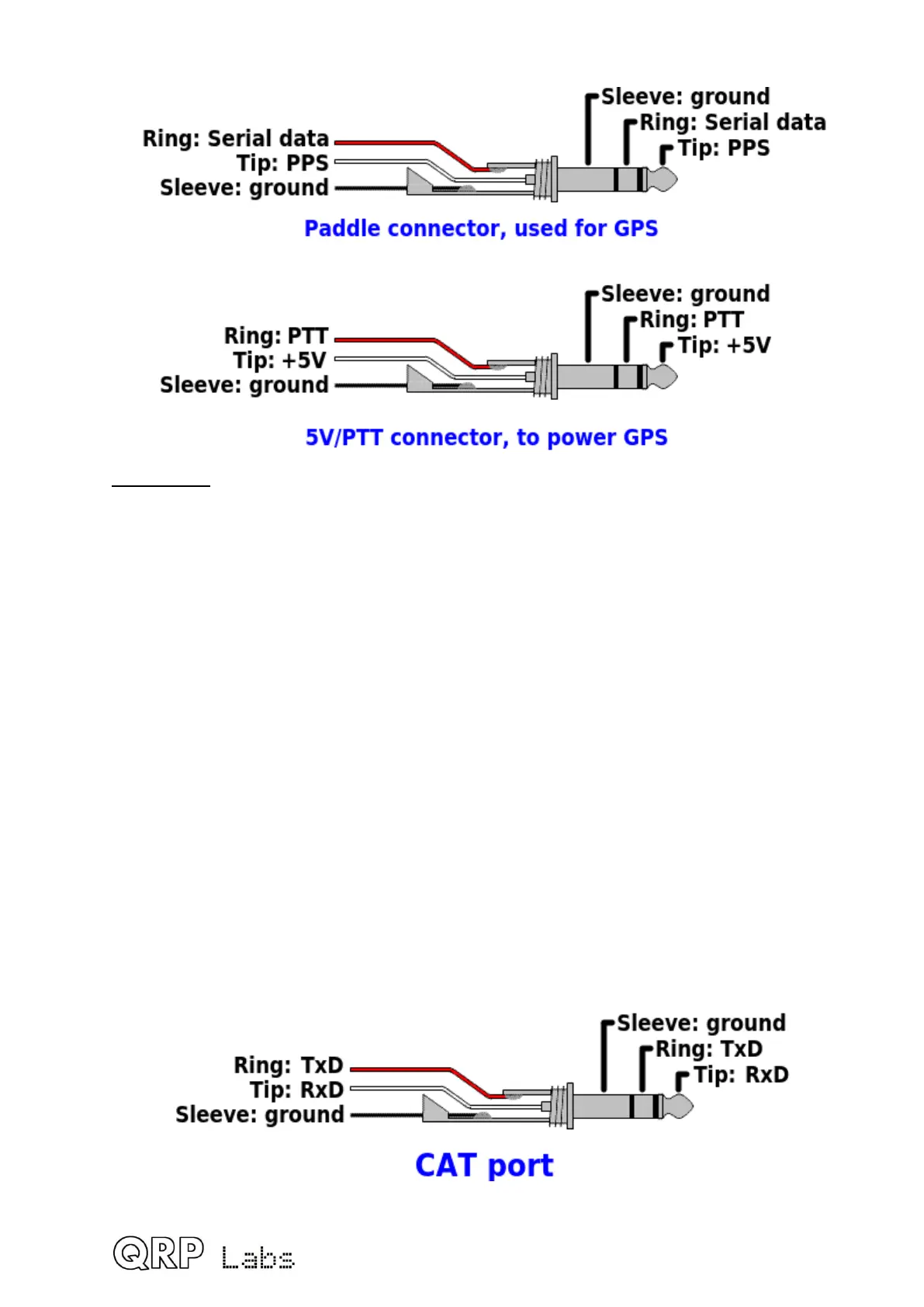
The following diagram shows the connections.
PTT output
The PTT output is at the ring of the 5V/PTT connector jack. This signal is 0V when the
QCX-mini is in Receive mode, and +5V when the QCX-mini is in Transmit mode. If you are
connecting the QCX-mini to the companion 50W PA kit, then this signal has to be
connected to the 50W PA kit to cause it to switch to Transmit mode. A standard 3.5mm
stereo audio cable can be used (having a 3.5mm stereo jack plug on each end).
Note that the pinout of the 5V/PTT connector is not the same as the Rev1/2 QCX+
PCBs. In the QCX+, ring is +5V and tip is PTT. This has the disadvantage that plugging in
a cable while the QCX+ is powered, can short the +5V to ground. Another disadvantage is
that standard 3.5mm stereo audio cables can’t be used. For this reason, complete
compatibility was broken in this instance. If you wish to use a 50W PA kit with either QCX+
or QCX-mini, the QCX+ manual contains details of the very simple modification needed to
swap the tip and ring connections in the QCX+.
3.49 QCX-mini CAT port
The QCX-mini CAT port allows a PC or other CAT-enabled host to control every aspect of
the QCX-mini. Operation of this feature is detailed in the operating manual. The connection
diagram below shows the connections to the 3.5mm stereo jack socket connector on the
rear panel of the QCX-mini.
82
 Loading...
