6.10 Unwanted sideband rejection
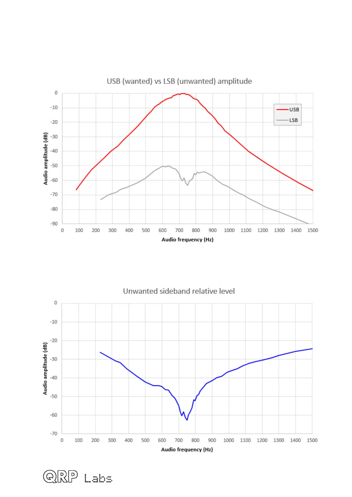
The following chart shows the measured level of the Upper Sideband signal (USB) and the
unwanted Lower Sideband signal (LSB) when tuning the receiver through a strong test
signal. The curves depend very heavily on the I-Q balance and audio phase shift
adjustments, and these curves are from one measured prototype.
Subtraction of these two curves results in the unwanted sideband level as shown in the
following chart. Normally anything above 40dB rejection is considered good; above 50dB is
excellent. With the built-in adjustment features of this kit it is relatively easy to achieve really
excellent unwanted sideband rejection.
119
 Loading...
