Solder each of the five switch pins, on the
underside of the PCB (the side with the blue
body of the rotary encoder). The center pin
of the three may benefit from a piece of wire
off-cut to extend it to reach the PCB hole.
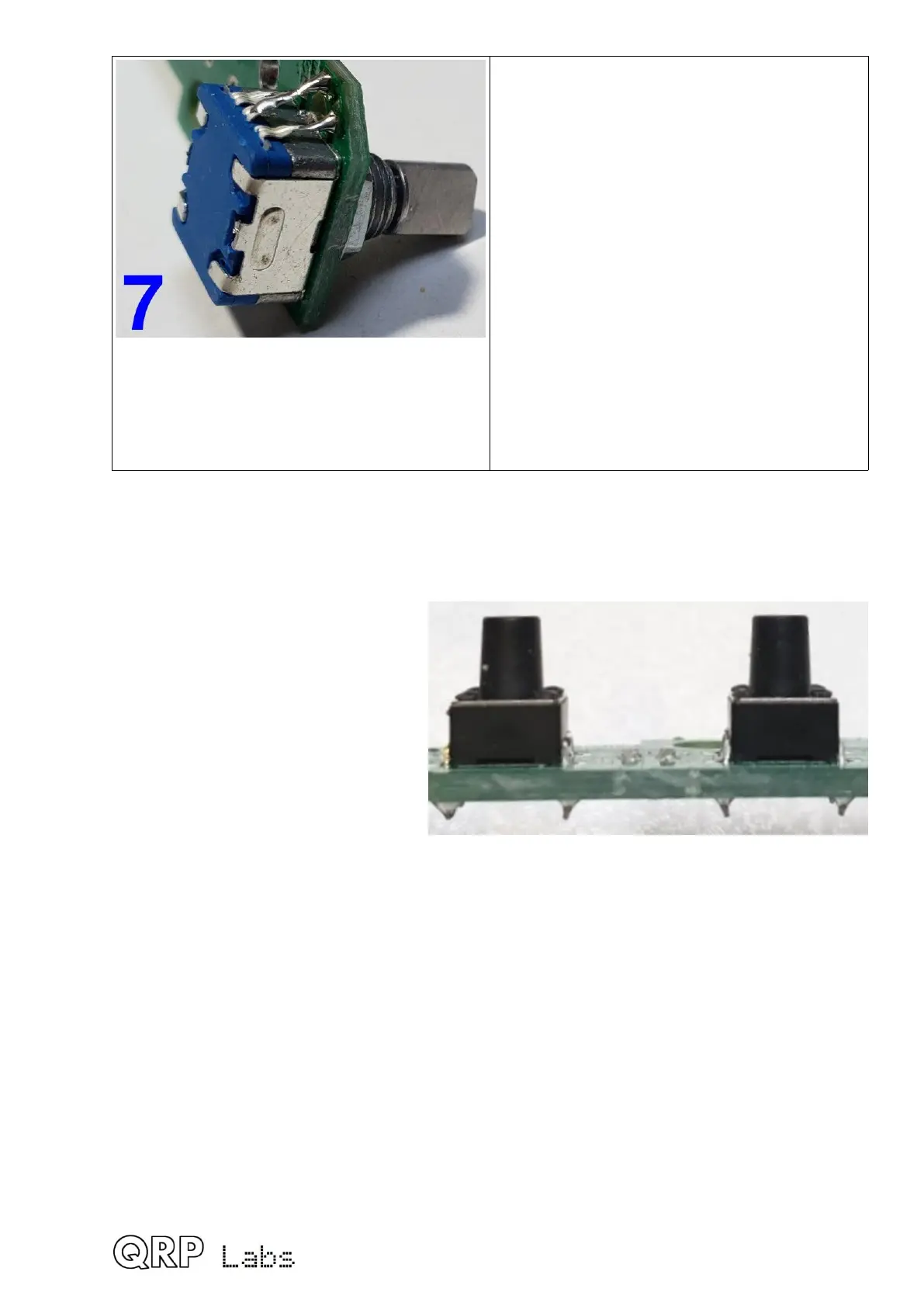
3.37 Install tactile switch buttons
The two buttons should be installed
on the control PCB as shown. These
have four pins on a rectangular
footprint that can only fit into the PCB
one way. The only special precaution
to observe here, is to make sure that
the switch button is seated squarely
on the PCB, so that the shaft is
perpendicular to the PCB. Solder two
diagonally opposite pins first then
check the alignment and make any
adjustments necessary; when all is
well, solder the two remaining pins.
3.38 Install gain control potentiometer R36
Remove the nut and washer from the potentiometer shaft. Install the potentiometer into the
position labeled R36. Align the potentiometer squarely with its locator tab in the provided
hole in the PCB. Secure the potentiometer in place with the washer and nut, and tighten.
The pins of the potentiometer will not reach the PCB however much you bend them.
Therefore it is necessary to bridge the gap between the pins and the PCB holes using
component off-cut wires. Just keep the pins as they are, don’t attempt to bend them.
64
 Loading...
