Install component off-cut wires, soldering
first the PCB end then the potentiometer pin
end; make the connection as close to the
green potentiometer body as possible.
Trim any excess length of both the pins, and
the off-cut component wires. It is important
to trim these as close to the joint as possible
so that there are no shorts when the boards
are fitted into the enclosure.
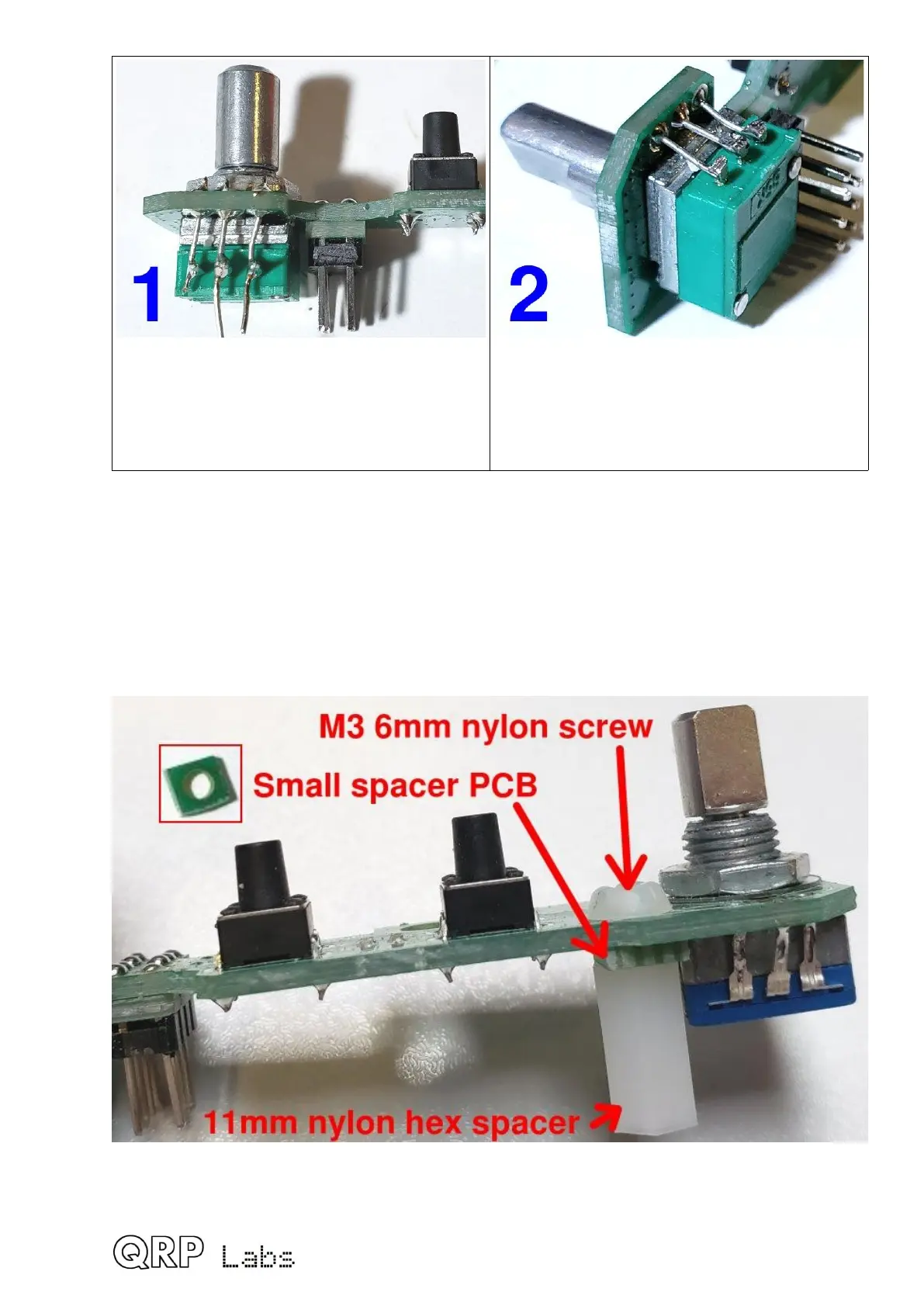
3.39 Install 11mm nylon hex spacer
The final 11mm nylon hex spacer is bolted to the controls PCB using an M3 6mm nylon
screw. Push the screw through the hole from the front side of the PCB. Thread the small
square spacer PCB that was broken out from the Display PCB panel, onto the screw. Then
screw on the 11mm nylon spacer.
This completes the Controls PCB assembly.
65
 Loading...
