Note that when using the TCXO module, the reference frequency setting must be
25,000,000 MHz, not the default which is 27,004,000 MHz. This is further described in
the initial set-up instructions, below. This is because the QCX-mini can operate either
with 25MHz reference (the TCXO module) or with 27MHz (the supplied crystal), BUT,
you have to tell it which one you have installed!
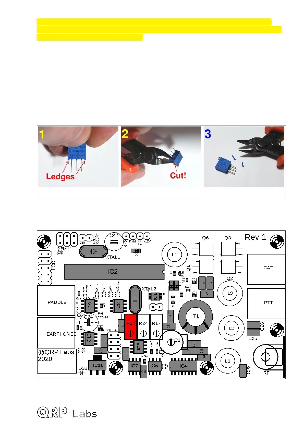
3.15 Install 500-ohm multi-turn trimmer potentiometer
This 24-turn trimmer resistor is the small blue box component with label “501”. It is R27.
The trimmer resistor has to be prepared carefully before installation. The resistor has little
ledges on either side which make it slightly too high to fit in the QCX-mini PCB assembly.
Therefore simply cut off these protrusions with a wire-cutter.
Note the ledges Cut ledge off with wire-cutter Enjoy less high trimmer pot!
The screw on the resistor must match the screw on the PCB silkscreen and layout diagram,
facing towards the lower edge of the board as drawn. Ensure it is firmly seated.
42
 Loading...
