3.35 Install 2x4-pin male header on controls PCB
Next comes the assembly of the controls PCB, which holds the gain control, rotary encoder
(frequency tuning), and the two tactile switch buttons.
The 2x4-pin header must be installed with the small spacer PCB sandwiched between the
connector body and the underside of the PCB. Carefully follow the steps below to install this
part.
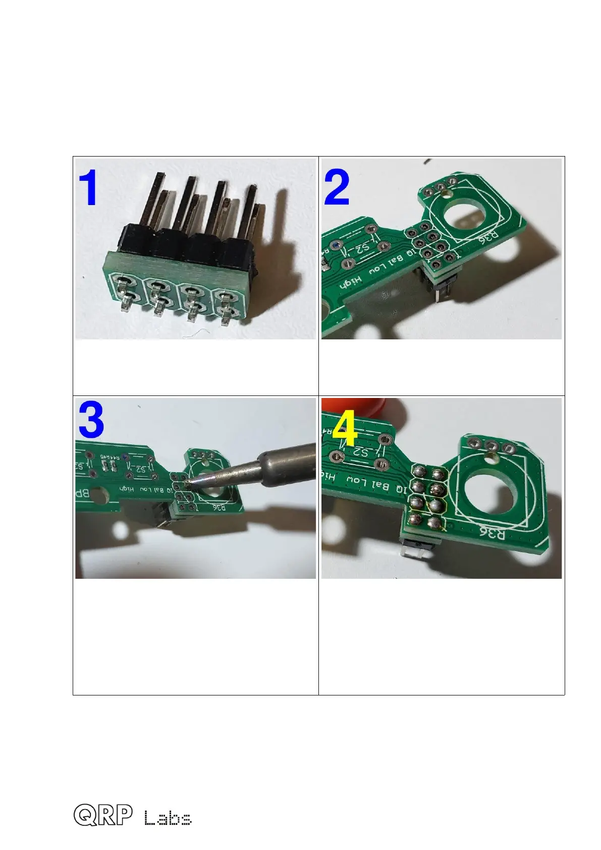
Thread the small spacer PCB having 8
matching holes, onto the short-pin side of
the 2x4-pin header.
Insert the remaining length of the short pins
into the PCB from the under-side, as shown.
The pins don’t protrude from the top side of
the holes. However the holes are through-
hole plated. Be generous with the solder,
and apply heat to the hole for at least 5
seconds to ensure the solder flows down
inside the hole and makes a good
connection to the pin.
Likewise, solder the remaining seven pins.
Don’t worry, this method really does work
reliably; just ensure the soldering iron is
poked into the hole if possible and apply
heat for at least 5 seconds on each joint,
and plenty of solder.
62
 Loading...
