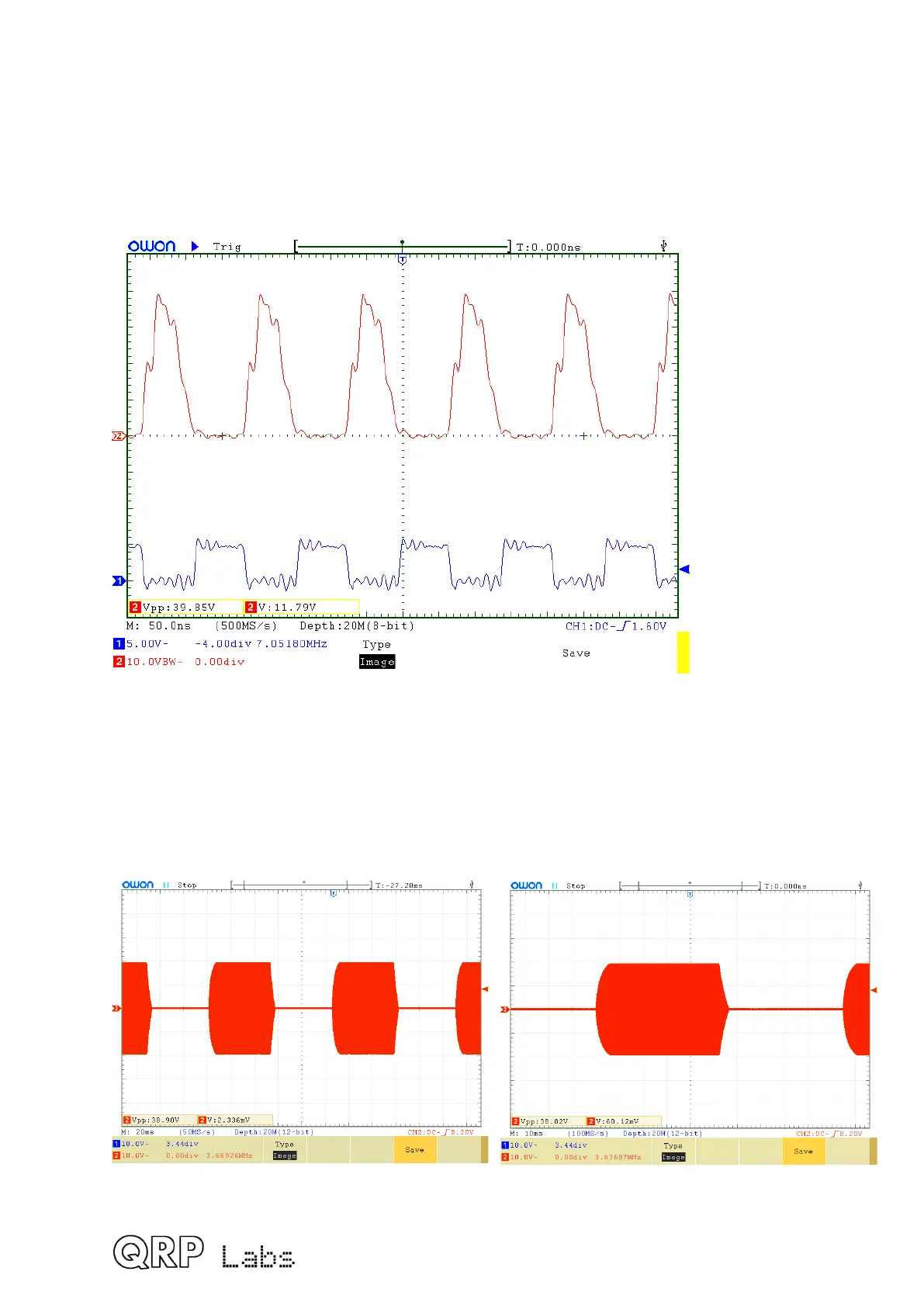
6.4 Class-E Power Amplifier drain waveform
This oscilloscope chart shows the waveform at the BS170 drains (top, RED colour trace)
and the input drive waveform, a 5V peak-peak squarewave (bottom, BLUE trace). The 40m
band is shown.
Upon ignoring the “ringing” artifacts due to poor ‘scope probes etc., the waveforms are
correct for Class-E operation.
6.5 RF envelope key-shaping
The following oscilloscope images show the RF envelope when keyed with a continuous 24
words per minute (50ms duration) string of dits. The simple key-shaping circuit described
earlier results in rise/fall times of around 5ms and significantly attenuates key-clicks.
113
 Loading...
