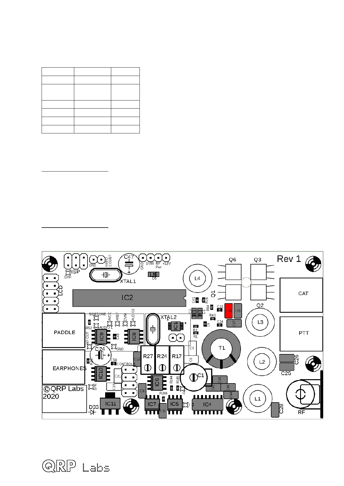
3.9 Install capacitor C30
This capacitor is band dependent. The kit contains all required capacitor values for all
bands. Install the one appropriate to your band. Refer to the following table to find the
correct capacitor value for your band
Band Value Label
80m 180pF “181”
60m 30pF
56pF
“300”
“560”
40m 56pF “560”
30m 30pF “300”
20m 30pF “300”
17m 30pF “300”
Note that for 40m and 80m versions, the 56pF and 180pF capacitors respectively,
may be packed in a separate small bag with the T37-2 and T50-2 toroids.
60m important note: for the 60m band, the capacitor requires both the 30pF and 56pF
capacitors to be soldered in parallel, but there is only one component position on the PCB.
For 60m, you will need to install one of the capacitors (e.g. 56pF) in the component holes
provided, and solder the other one (e.g. 30pF) to the same pads under the PCB. Take care
to keep the component wires short and not accidentally touching any other nearby
components or soldered pads.
80m important note: the 180pF capacitor supplied has a 0.2-inch (5.08mm) pin spacing.
But the holes on the PCB are spaced 0.1-inch (2.5mm). It is necessary to squeeze the
capacitors wires carefully closer together to fit the PCB holes.
35
 Loading...
