3.23 Install 2x4 UI header
This female pin header (socket) connects the main QCX-mini PCB to the
controls board above it. Solder one pin in place first and check that the header is
nicely seated on the PCB before soldering the other 8.
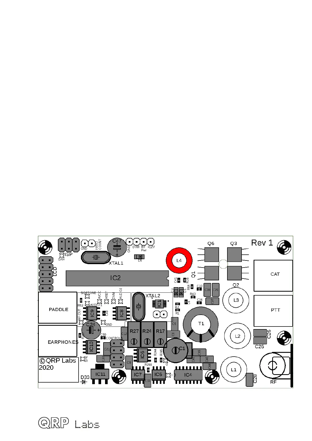
3.24 Wind and install toroid L4
L4 is type T37-2. It is a small ring with red paint on one side. Each time the wire passes
through the hole in the middle of the toroid, this counts as one turn. The number of turns
depends on the band of your kit, refer to the following table. Inductance values are
approximate and will depend on variations in the core, and how tightly you wind the turns.
Do not worry about these variations which are not critical in this case.
Band Value Turns
80m 2.3uH 24
60m 2.3uH 24
40m 1.0uH 16
30m 0.78uH 14
20m 0.40uH 10
17m 0.32uH 9
Try to keep the wire quite tight (but not so tight that you break the wire). Try to spread the
turns evenly around the toroid. Leave about 2cm or 3cm of wire at the ends.
The wire is coated with an enamel insulating paint and it is CRITICAL to remove this
enamel at the soldered joints otherwise there will be no electrical connection through
50
 Loading...
