6.3 Transmitter power output
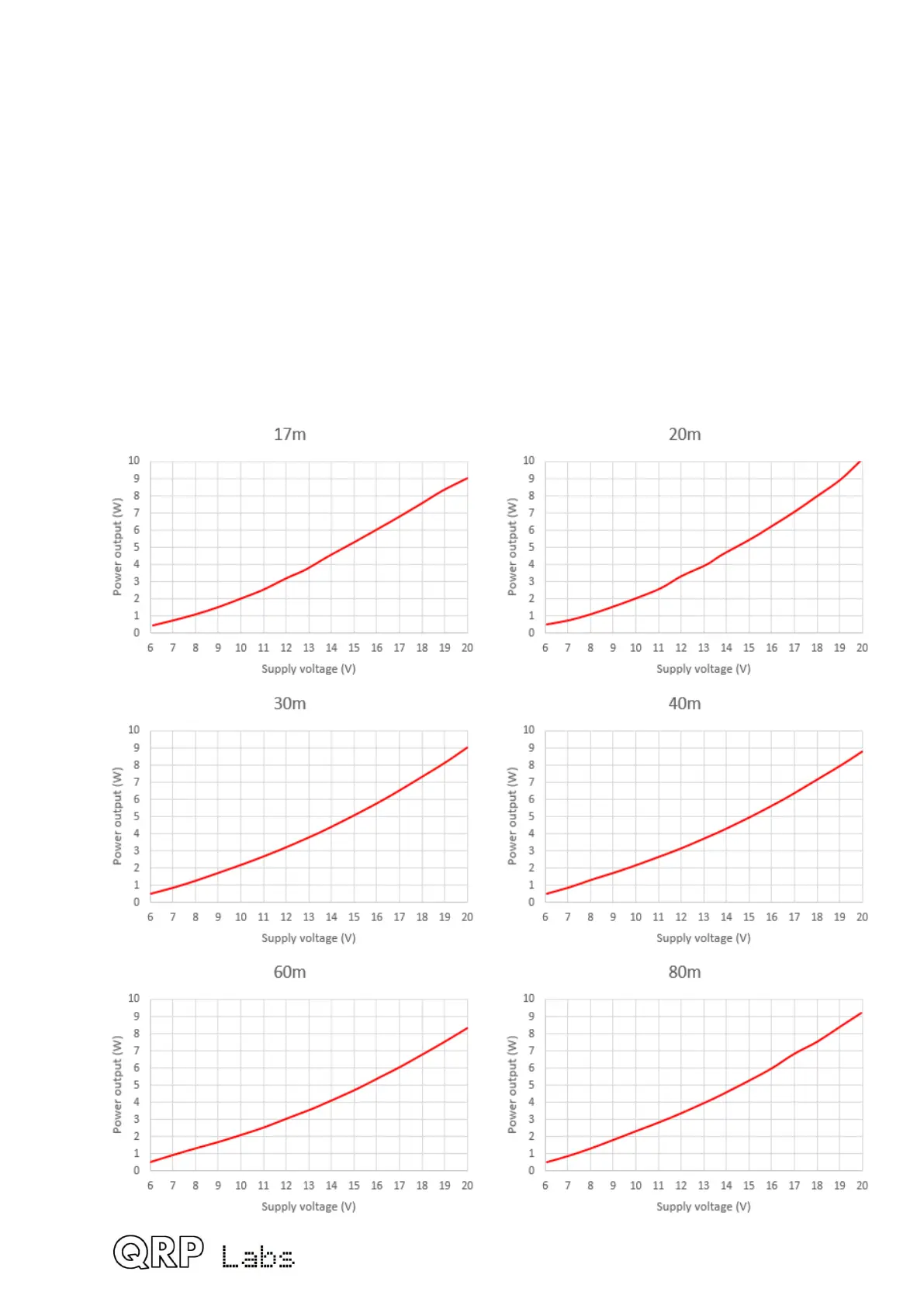
The transmitter RF power output varies depending on the power supply voltage. It is also
dependent on band. Your results may vary depending on your Low Pass Filter inductor
construction! If the cut-off frequency becomes too low, then you can start to get attenuation
at the operating frequency. In this case you can remove a turn or two from each toroid.
The following charts show the power measurement using the oscilloscope to measure the
peak-peak amplitude across the 50-ohm dummy load.
Operation at output power levels above 5W is NOT recommended, as it will put too much
strain on the BS170 output transistors which may result in failure. For this reason, limiting
the supply voltage to not more than 14V.
Note that these measurements do not take into account the D33 1N5819 reverse polarity
protection diode voltage drop (approximately 0.3 or 0.4V). In other words, the
measurements were done in a transceiver with D33 bypassed by a wire link.
112
 Loading...
