3.20 Install three BS170 transistors
The remaining three transistors in the kit are
BS170 MOSFETs: Q1, Q2 and Q3
For Q1, Q2 and Q3, carefully follow the same
installation procedure as the previous section,
making sure that the transistors are neatly
aligned in the correct positions near the hole in
the PCB.
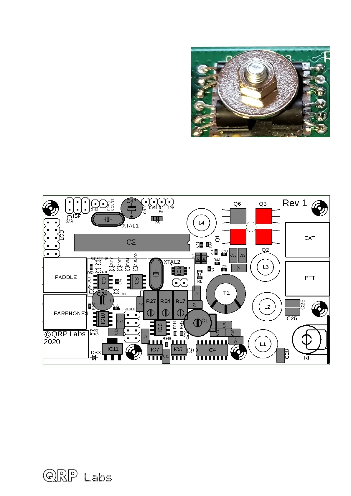
After installation, use the supplied 10mm
M3 steel screw, 12mm steel washer and
M3 nut to bolt the transistors’ flat sides
firmly flat on the PCB surface, as shown
(photo, right).
The kit may contain both a 10mm screw AND a 12mm screw. It is essential to use the
10mm screw, not the 12mm screw (which is too tall). 10mm is the desired length of
the threaded section.
47
 Loading...
