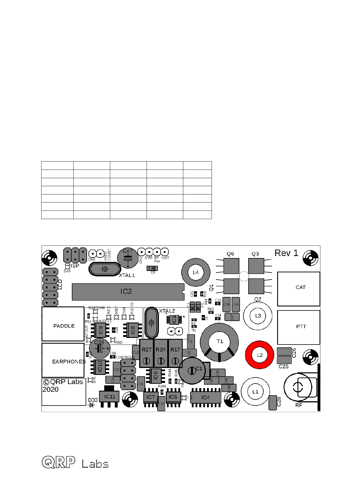
3.25 Wind and install toroid L2
L2 is a small toroid ring painted yellow or red on one side. It is part of the supplied Low
Pass Filter kit bag. Installation of the inductor is similar to the previous section. Remember
to remove the wire enamel and check!
In the QCX-mini kit, there is some advantage to winding the toroid with the turns
tightly squeezed together, then installing it, and only then spreading them out
evenly. This is because you will probably later want to try squeezing and expanding the
turns of the toroids to optimize output power. The way the toroids are installed laying flat on
the PCB in the QCX-mini, it’s much easier to spread out the turns if they were initially
bunched together, than it would be to bunch them up if they were initially spread out. In the
latter case the wire will be rather tight to try and bunch up the turns.
The number of turns is band-dependent, refer to the following table. Inductance values are
approximate and will depend on variations in the core, and how tightly you wind the turns.
Do not worry about these variations which are not critical in this case.
Band Toroid Colour Value Turns
80m T37-2 Red 3.0uH 27
60m T37-2 Red 2.3uH 24
40m T37-6 Yellow 1.7uH 24
30m T37-6 Yellow 1.3uH 20
20m T37-6 Yellow 0.90uH 17
17m T37-6 Yellow 0.67uH 15
52
 Loading...
