Home
QRP Labs
Transceiver
QCX-mini
QRP Labs QCX-mini Assembly Instructions
4
of 1
of 1 rating
121 pages
Give review
Manual
Specs
To Next Page
To Next Page
To Previous Page
To Previous Page
Loading...
3.5
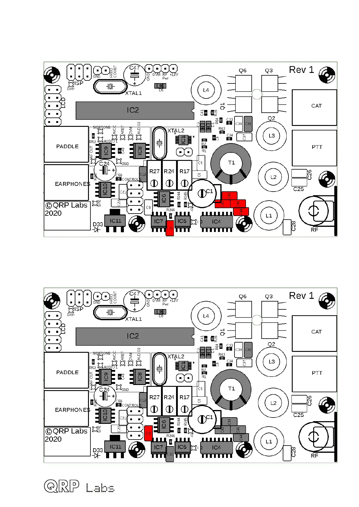
Install all 470nF, “474” capacitors
The five 470nF capacitors are labeled “474”, and are capacitors C11, C4
3, C44, C45 and
C46.
3.6
Install 47nF, “473” capacitor
The 47nF (0.047uF) capacitor is labeled “473” and is capacitor C9.
32
31
33
Table of Contents
Table of Contents
2
Introduction
4
Parts List
5
Assembly - General Guidelines
10
Inventory Parts
22
Wind and Install Transformer T1
23
Install IC2 Socket
30
Install 100Nf (0.1Uf, "104") Capacitors
31
Install All 470Nf, "474" Capacitors
32
Install 47Nf, "473" Capacitor
32
Install Capacitors C25 and C26 from Low Pass Filter Kit
33
Install Capacitors C27 and C28 from Low Pass Filter Kit
34
Install Capacitor C30
35
Install Capacitors C5 and C8
36
Install 1Uf, "105" Capacitors C21, and C22
37
Install 1N5819 Diode
38
Install 20Mhz Crystal XTAL1
39
Install 27Mhz Crystal XTAL2 or TCXO Option
40
Install 500-Ohm Multi-Turn Trimmer Potentiometer
42
Install 50K Multi-Turn Trimmer Potentiometers
43
Install 470Uf Capacitors
44
Install 30Pf Trimmer Capacitor C1
45
Install MPS751 Transistor Q6
46
Install Three BS170 Transistors
47
Install 2X3-Pin In-Circuit Programming Header
48
Install 2X5 LCD Header
49
Install 2X4 UI Header
50
Wind and Install Toroid L4
50
Wind and Install Toroid L2
52
Wind and Install Toroids L1 and L3
53
Install 2.1Mm Power Connector
54
Install RF Output BNC Connector
55
Install 3.5Mm Stereo Jack Connectors
56
Break Apart Inner Pcbs of Display Board
57
Install LCD Module
59
Install 2X5-Pin Male Pin Header Connector
60
Install Four 11Mm Nylon Spacers
60
Install 20K Trimmer Potentiometer R47
61
Install 2X4-Pin Male Header on Controls PCB
62
Install Rotary Encoder
63
Install Tactile Switch Buttons
64
Install Gain Control Potentiometer R36
64
Install 11Mm Nylon Hex Spacer
65
Fit Controls PCB to Main PCB
66
Install Microcontroller
67
10Uf Input Capacitor C38
67
Plug Together the Two Boards
70
Connections for Basic Operation
70
Notes on Fault-Finding for the QCX-Mini
71
Adjustment and Alignment
72
Installation in the Optional QCX-Mini Enclosure
78
QCX-Mini GPS Interface and PTT Output
81
QCX-Mini CAT Port
82
Circuit Design of the QCX-Mini
83
Block Diagram and Summary
83
Circuit Diagram
83
Synthesized Oscillator
86
Transmit/Receive Switch
87
Band Pass, Phase Splitter, QSD and Pre-Amps
88
90-Degree Audio Phase Shift
89
CW Filter
90
Audio Amplifier
90
Transmit Signal Routing and PA Driver
92
Class-E Power Amplifier
93
Low Pass Filter
94
Key-Shaping Circuit
95
Microcontroller
96
Optional GPS Interface
102
In Circuit Programming (ISP) Interface
103
Test Equipment
103
Voltage Regulator
105
Fault-Finding
106
Blank LCD or Blocked LCD
106
No Back-Light at All
106
A Row of Blocks Appears on the Top Row
106
DC Voltage Readings
106
RF Power Output Check
109
Measurements
111
Equipment
111
Transceiver Current Consumption
111
Transmitter Power Output
112
Class-E Power Amplifier Drain Waveform
113
RF Envelope Key-Shaping
113
Low Pass Transmitter Harmonic Output Filter Characteristics
114
Band Pass Receiver Input Filter Characteristics
114
Quadrature Sampling Detector Bandwidth
117
CW Filter Response
118
Unwanted Sideband Rejection
119
Operation Reference "Cheat Sheet
120
Resources
121
Document Revision History
121
Other manuals for QRP Labs QCX-mini
Operating Instructions
52 pages
4
Based on 1 rating
Ask a question
Give review
Questions and Answers:
Need help?
Do you have a question about the QRP Labs QCX-mini and is the answer not in the manual?
Ask a question
QRP Labs QCX-mini Specifications
General
Brand
QRP Labs
Model
QCX-mini
Category
Transceiver
Language
English
Related product manuals
QRP Labs QCX
52 pages
QRP Labs QDX
38 pages
QRP Labs QMX
90 pages
 Loading...
