INSTALLATION
Harmony Ball Return Manual – 400-254-022 11 Rev. Date 3/16
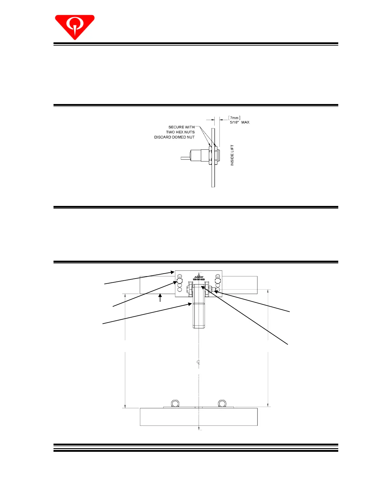
6.3 INSTALLING THE BALL ENTRY SENSOR
Install the ball entry sensor through the hole in the side plate as shown in Figure 5. Adjust the
nuts so that the face of the sensor does not protrude more than 5/16” [7mm] into the lift.
Tighten nuts using the provided wrenches.
Figure 5, Ball Entry Sensor
6.4 INSTALLING THE BALL STOP
Install the ball stop on the 2x4 leveler inside the lane side trap door as shown in Figure 6.
Figure 6, Ball Stop Installation
SCREW, LAG 5/16x1-1/2
810-556-240
BOLT, HEX 5/16-18x2
809-857-325
NUT, STOVER, 5/16-18
844-057-002
 Loading...