INSTALLATION
Harmony Ball Return Manual – 400-254-022 27 Rev. Date 3/16
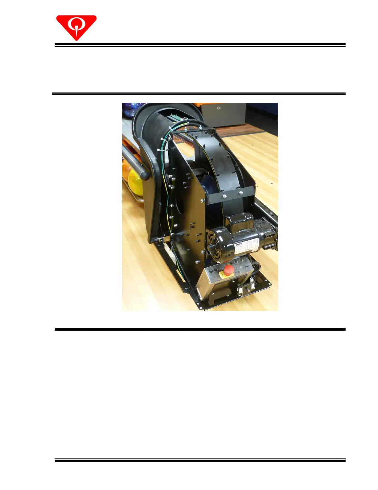
22. Route the cables from the sensor control board along the even-lane side of the ball lift to
the lift control box through the designated entry point. Secure cable ties as required to
keep the wires out of the path of the ball or any moving parts. See Figures 21 and 22.
Restrain the cables to the bezel with cable ties as shown in Figure 22.
Figure 22, Intrusion Sensor Cable Routing
23. Plug the sensor board cable into JP6 Ball Exit Sensor on the control board. Secure the
ground wire on its own ground stud inside of the control box.
 Loading...