Home
QubicaAMF
Sports & Outdoors
Harmony
QubicaAMF Harmony User Manual
5
of 1
of 1 rating
72 pages
Give review
Manual
Specs
To Next Page
To Next Page
To Previous Page
To Previous Page
Loading...
P
ARTS
Harmony
Ball Return
M
anual
–
400
-
254
-
02
2
Rev. Date 3/16
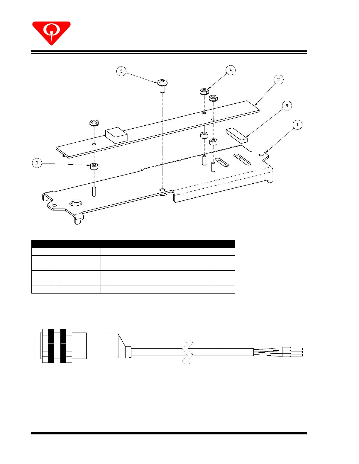
60
252
-
003
-115
,
Hand In
trusion Sensor Assembly
Part No.
Description
Qty
1
254
-001-
124
Harmony H.I.S. Groun
d Plate Assembly
1
2
252
-003-
104
Intrusion & Ball E
xit Sensor Board Assembly
1
3
722
-503-
097
SFR 0.12 X 0.25 X 0.
13 ZN
3
4
843
-121-
002
KN 4-40 ZN
3
5
818
-233-
052
PHPMS 8-32 X 0.31 ZN SE
MS
1
6
252
-003-
117
1/4 X 1/8 X 1 Self-Adh
esive Foam
1
254
-
001
-069
,
Ball E
ntry Sensor Assembly
69
71
Table of Contents
Default Chapter
7
Table of Contents
7
1 How to Use this Manual
11
2 Introduction
11
3 Packing Lists and Tools
12
4 Safety
13
U.s.a
13
Warnings/Symbols
14
5 Transportation
16
Lift Points
16
6 Installation
17
Approach Opening
17
Figure 1, Approach Opening Layout - Top View
17
Harmony Ball Lift Installation
18
Figure 2, Standard Layout & Rack-Bezel Support
18
Figure 3, Ball Lift Mounting Requirements
19
Figure 4, Track to Lift Connection
20
Installing the Ball Entry Sensor
21
Installing the Ball Stop
21
Figure 5, Ball Entry Sensor
21
Figure 6, Ball Stop Installation
21
Installing the Hood Assembly
22
Figure 7, Harmony Hood Assembly
22
Figure 8, Hood Base
23
Figure 9, Hood to Base Connection
23
Figure 10, Rack-Bezel Support and Hood Adjustment
24
Installing the Blower and Hood Switch
25
Figure 11, Blower Installation
25
Figure 12, Hood Switch Installation
26
Installing the Ball Lift Control Box
27
Figure 13, Control Box Fuse Label
27
Figure 14, Control Box Installation
27
Installing the Ball Rack and Optional Lower Rack
28
Figure 15, Lower Ball Rack Mounting
28
Figure 16, Rack to Ball Lift Attachment
29
Figure 17, Rack Pedestal Installation
30
Connecting the Wiring
31
Figure 18, Control Box Fuse Label
31
Figure 19, Control Box Wiring Diagram
33
Blower Connections
34
Lift Motor Connections
34
Main AC Power Connections
34
Figure 20, Control Box Wiring - Pinspotters
35
Pinspotter Connections
35
Figure 21, Intrusion Sensor Installation
36
Hood Switch Connections
36
Intrusion Sensor Installation
36
Figure 22, Intrusion Sensor Cable Routing
37
Ball Entry Sensor Connections
38
Optional 10 Th Frame Switch
38
Electrical Ratings
39
Figure 23, Nameplate Data
39
7 Setup and Testing
40
8 Operation
41
Operational Safety
41
Ball Lift Controls
41
Errors
42
Figure 24, Control Box Display
42
Software
44
9 Cleaning and Care
45
Ball Rack Tray
45
Ball Return Hood
45
10 Service
46
11 Troubleshooting
47
Drawings & Parts Lists
49
Harmony Ball Lift with Parts Kit
51
Harmony Ball Lift View-1
52
Harmony Ball Lift View-2
53
Harmony Ball Lift View-3
54
610-049-511, Underlane Track Shim Kit
56
254-001-302, Even Side Plate Assembly
57
254-001-301 - Odd Side Plate Assembly
58
254-001-175, Lower Guide Assembly
59
254-001-176 - Upper Guide Assembly
60
Motor & Bracket Assembly
61
250-001-396 - Lower Shaft Assembly
62
254-001-191-XX, Hood Set
63
Hood Frame
64
254-001-182 - Ball Rack Assembly
65
254-001-048 - Ball Rack Blower Assembly
66
254-001-045 - Harmony Rack-Support Mount Kit
67
Ball Rack Pedestal & Lower Rack
67
611-353-105 - Ball Stop Latch Kit
68
Hand Intrusion Sensor Kit & Hood Switch Kit
69
252-003-115 - Hand Intrusion Sensor Assembly
70
254-001-069 - Ball Entry Sensor Assembly
70
Control Box Replacement Parts
71
Electrical Schematic
72
5
Based on 1 rating
Ask a question
Give review
Questions and Answers:
Need help?
Do you have a question about the QubicaAMF Harmony and is the answer not in the manual?
Ask a question
QubicaAMF Harmony Specifications
General
Brand
QubicaAMF
Model
Harmony
Category
Sports & Outdoors
Language
English
Related product manuals
QubicaAMF Options Ball Return
46 pages
QubicaAMF 90XLi
42 pages
TMS Tenpin String Pinspotter
155 pages
 Loading...