14. Serial I/O
puorG92/C61M
page 191
854fo7002,03.raM21.1.veR
2110-1010B90JER
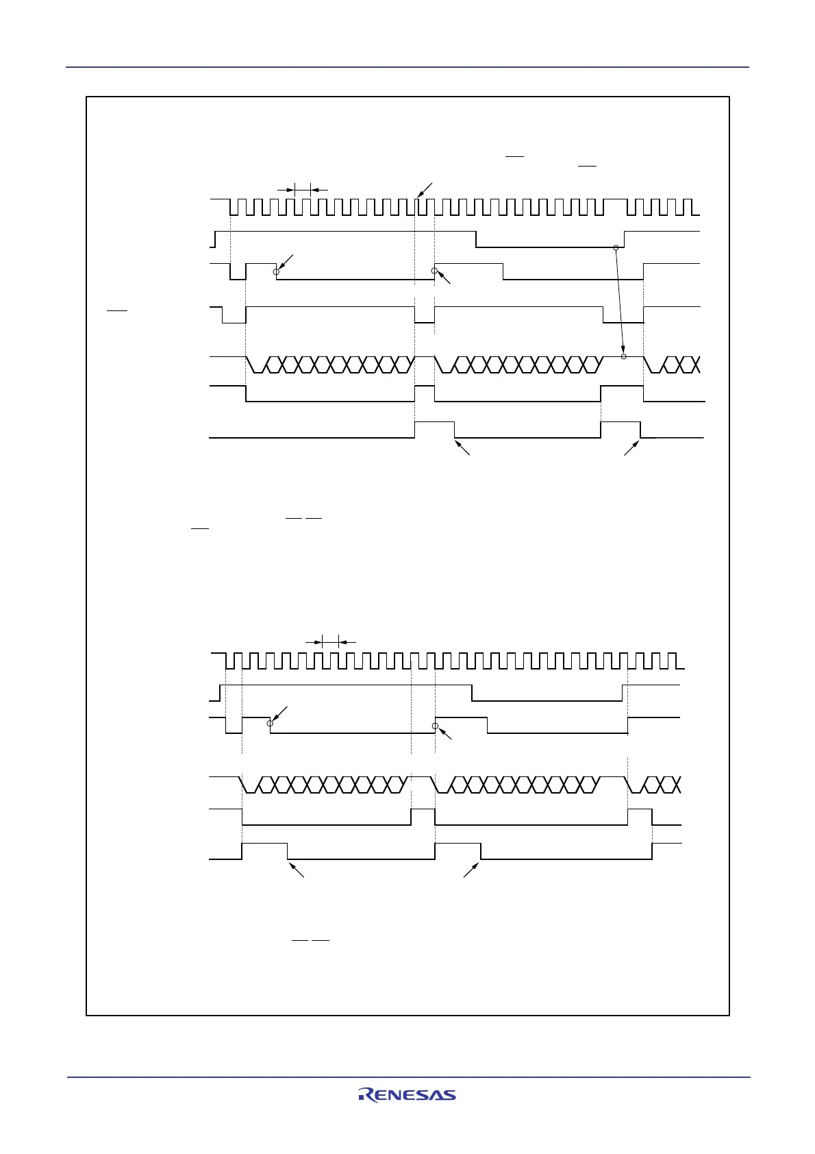
Figure 14.16 Typical transmit timing in UART mode (UART0, UART1)
Start
bit
Parity
bit
TxDi
CTSi
1
0
1
“L”
“H”
0
1
0
1
TxDi
0
1
0
1
0
1
Transfer clock
Tc
0
1
Tc
Transfer clock
D
0
D
1
D
2
D
3
D
4
D
5
D
6
D
7
ST PD
0
D
1
D
2
D
3
D
4
D
5
D
6
D
7
SP ST
P
SP
D
0
D
1
ST
Stop
bi
t
Start
bit
The transfer clock stops momentarily as CTSi is “H” when the stop bit is checked.
The transfer clock starts as the transfer starts immediately CTSi changes to “L”.
D
0
D
1
D
2
D
3
D
4
D
5
D
6
D
7
ST
SP
D
8
D
0
D
1
D
2
D
3
D
4
D
5
D
6
D
7
ST
D
8
D
0
D
1
ST
SPSP
Stop
bit
Stop
bit
0
SP
Stopped pulsing
because the TE bit
= “0”
Write data to the UiTB register
UiC1 register
TE bit
UiC1 register
TI bit
UiC0 register
TXEPT bit
SiTIC register
IR bit
Transferred from UiTB register to UARTi transmit register
The above timing diagram applies to the case where the register bits
are set as follows:
• Set the PRYE bit in the UiMR register to 1 (parity enabled)
• Set the STPS bit in the UiMR register to 0 (1 stop bit)
• Set the CRD bit in the UiC0 register to 0 (CTS/RTS enabled),
the CRS bit to 0 (CTS selected).
• Set the UiIRS bit to 1 (an interrupt request occurs when transmit completed):
U0IRS bit is the UCON register bit 0, U1IRS bit is the UCON
register bit 1, and U2IRS bit is the U2C1 register bit 4
Cleared to 0 when interrupt request is accepted, or cleared to 0 by program
UiC1 register
TE bit
UiC1 register
TI bit
UiC0 register
TXEPT bit
SiTIC register
IR bit
Cleared to 0 when interrupt request is accepted, or cleared to 0 by program
Write data to the UiTB register
Transferred from UiTB register to UARTi
transmit register
The above timing diagram applies to the case where the register bits are
set as follows:
• Set the PRYE bit in the UiMR register to 0 (parity disabled)
• Set the STPS bit in the UiMR register to 1 (2 stop bits)
• Set the CRD bit in the UiC0 register to 1 (CTS/RTS disabled)
• Set the UiIRS bit to 0 (an interrupt request occurs when transmit buffer
becomes empty):
U0IRS bit is the UCON register bit 0, U1IRS bit is the UCON
register bit 1, and U2IRS bit is the U2C1 register bit 4
• Example of transmit timing when transfer data is 9-bit long (parity disabled, two stop bits)
• Example of transmit timing when transfer data is 8-bit long (parity enabled, one stop bit)
Tc = 16 (n + 1) / fj or 16 (n + 1) / f
EXT
fj: frequency of UiBRG count source (f
1SIO
, f
2SIO
, f
8SIO
, f
32SIO
)
f
EXT
: frequency of UiBRG count source (external clock)
n: value set to UiBRG
i = 0 to 2
Tc = 16 (n + 1) / fj or 16 (n + 1) / f
EXT
fj: frequency of UiBRG count source (f
1SIO
, f
2SIO
, f
8SIO
, f
32SIO
)
f
EXT
: frequency of UiBRG count source (external clock)
n: value set to UiBRG
i = 0 to 2
 Loading...


