14.Serial I/O
puorG92/C61M
page 190
854fo7002,03.raM21.1.veR
2110-1010B90JER
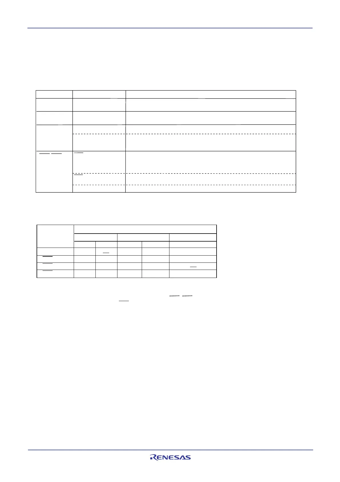
Table 14.7 lists the functions of the input/output pins in UART mode. Table 14.8 lists the P64 pin func-
tions during UART mode. Note that for a period from when the UARTi operation mode is selected to when
transfer starts, the TxDi pin outputs an “H”. (If the N-channel open-drain output is selected, this pin is in a
high-impedance state.)
Table 14.7 I/O Pin Functions in UART mode
(1)
Table 14.8 P64 Pin Functions in UART mode
(1)
Pin Name Function Method of Selection
TxDi (i = 0 to 2)
(P6
3
, P6
7
, P7
0
)
Serial data output
Serial data input
Input/output port
Transfer clock input
Input/output port
(Outputs "H" when performing reception only)
RxDi
(P6
2
, P6
6
, P7
1
)
CLKi
(P6
1
, P6
5
, P7
2
)
Set the CKDIR bit in the UiMR register to 0
Set the CKDIR bit in the UiMR register to 1
Set the PD6_1 bit and PD6_5 bit in the PD6 register to 0, PD7_2 bit in the PD7
register to 0
PD6_2 bit, PD6_6 bit in the PD6 register and the PD7_1 bit in the PD7 register
(Can be used as an input port when performing transmission only)
Set the CRD bit in the UiC0 register to 0
Set the CRS bit in the UiC0 register to 0
Set the PD6_0 bit and PD6_4 bit in the PD6 register to 0, the PD7_3 bit in the
PD7 register 0
Set the CRD bit in the UiC0 register to 0
Set the CRS bit in the UiC0 register to 1
Set the CRD bit in the UiC0 register 1
CTS input
RTS output
CTSi/RTSi
(P6
0
, P6
4
, P7
3
)
NOTE:
1. When the U1MAP bit in PACR register is set to 1 (P7
3
to P7
0
), UART1 pin is assgined to P7
3
to P7
0
.
Pin Function
Bit Set Value
U1C0 register
UCON register
PD6 register
CRD
CRS
RCSP
CLKMD1
PD6_4
P6
4
1 0 0 Input: 0, Output: 1
CTS
1 0000
RTS1
10 0
CTS
0
(2)
0
0
0
00 10
NOTES:
1. When the U1MAP bit in PACR register is 1 (P7
3 to P70), this table lists the P70 functions.
2. In addition to this, set the CRD bit in the U0C0 register to 0 (CTS
0/RTS0 enabled) and the
CRS bit in the U0C0 register to 1 (RTS
0 selected).
 Loading...


