10
10-132
MULTIJUNCTION TIMERS
10.6 TML (Input-Related 32-Bit Timer)
32180 Group User’s Manual (Rev.1.0)
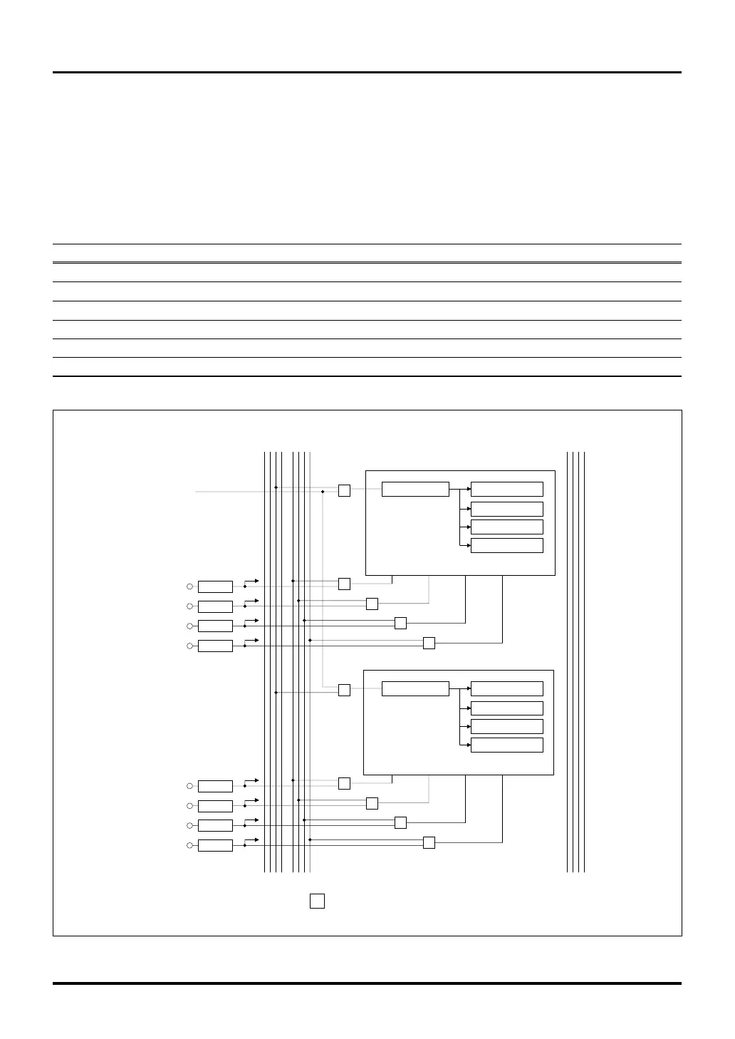
Figure 10.6.1 Block Diagram of TML (Input-Related 32-Bit Timer)
Clock bus Input event bus
3 2 1 0 3 2 1 0
S
S
S
S
TIN20S
TIN21S
TIN20 (P134)
TIN21 (P135)
TIN22S
TIN22 (P136)
TIN23S
TIN23 (P137)
IRQ11
IRQ11
IRQ11
IRQ11
BCLK/2
Output event bus
0 1 2 3
S
: Selector
3 2 1 0 3 2 1 0 0 1 2 3
clk
TML0
cap3 cap2 cap1 cap0
Measure register 3
Counter
(32-bit)
S
S
S
S
S
TIN30S
TIN31S
TIN30 (P194)
TIN31 (P195)
TIN32S
TIN32 (P196)
TIN33S
TIN33 (P197)
IRQ18
IRQ18
IRQ18
IRQ18
clk
TML1
cap3 cap2 cap1
cap0
S
Measure register 2
Measure register 1
Measure register 0
Measure register 3
Measure register 2
Measure register 1
Measure register 0
Counter
(32-bit)
10.6 TML (Input-Related 32-Bit Timer)
10.6.1 Outline of TML
TML (Timer Measure Large) is an input-related 32-bit timer capable of measuring input pulses in two circuit
blocks comprising a total of eight channels.
The table below shows specifications of TML. The diagram in the next page shows a block diagram of TML.
Table 10.6.1 Specifications of TML (Input-Related 32-Bit Timer)
Item Specification
Number of channels 8 channels (2 circuit blocks consisting of 4 channels each, 8 channels in total)
Input clock BCLK/2 (10.0 MHz when f(BCLK) = 20 MHz) or clock bus 1 input
Counter 32-bit up-counter × 2
Measure register 32-bit measure register × 8
Timer startup Start counting immediately after reset

 Loading...


