13-73
13
32180 Group User’s Manual (Rev.1.0)
CAN MODULE
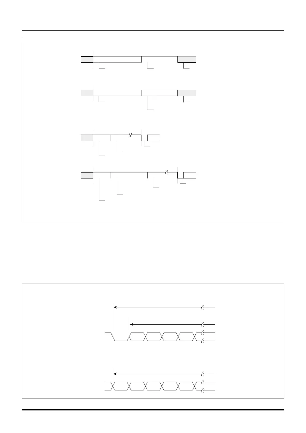
Figure 13.3.2 CAN Protocol Frames (2)
13.3 CAN Protocol
Error flag Error delimiter
Interframe space or overload flag
6–12
8
Overload flag
Overload delimiter
6–12
8
Interframe space or overload flag
Error frame
Overload frame
Interframe space
Intermission
Bus idle
SOF of the next frame
For the case of an error active state
3
0–
Suspend transmission
For the case of an error passive state
3
8
0–
SOF of the next frame
Bus idle
Intermission
Note: • The number in each field denotes the number of bits.
1
1
13.3.2 Data Formats during CAN Transmission/Reception
Figure 13.3.3 shows an example of the transmit/receive transfer data format that can be used in CAN. Data is
transmitted/received sequentially beginning with the MSB side of the CAN message slot (C0MSLnSID0–
C0MSLnDT7, C1MSLnSID0–C1MSLnDT7).
Figure 13.3.3 Example of a CAN Transmit/Receive Transfer Data Format
SOF SID0 SID1 SID2 SID3
MSB
Arbitration field
CAN frame
Arbitration field
b0 b1 b2 b3 b4
MSB
Data field
Data field

 Loading...


