14
14-10
REAL TIME DEBUGGER (RTD)
14.3 Functional Description of the RTD
32180 Group User’s Manual (Rev.1.0)
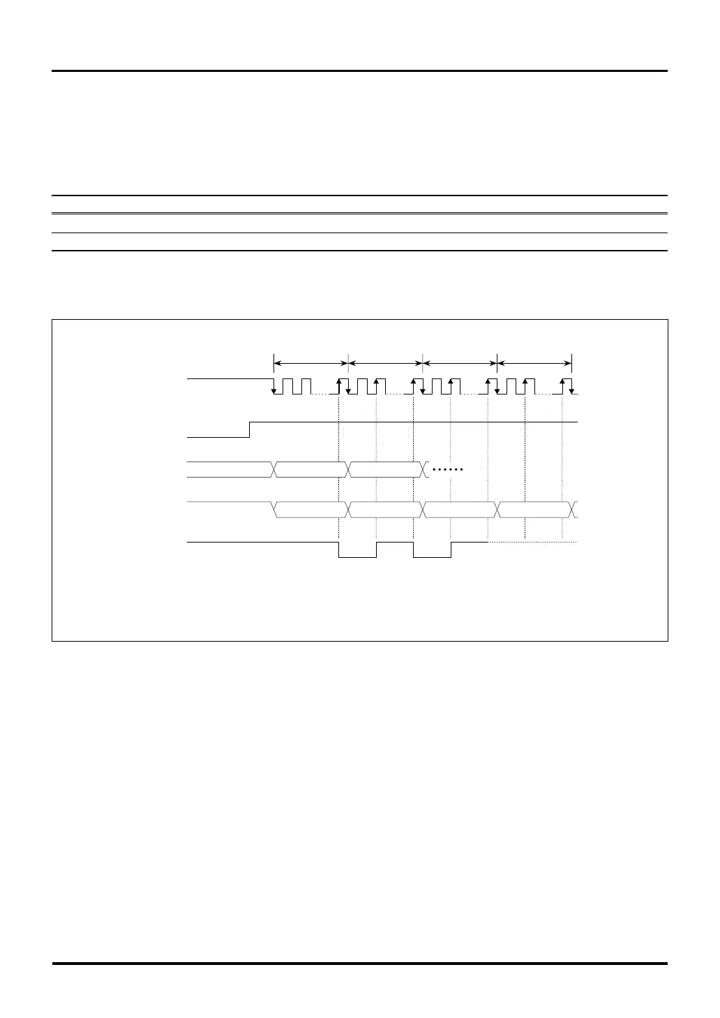
14.3.8 Resetting the RTD
The RTD is reset by applying a system reset (i.e., RESET# signal). The status of the RTD related output pins
after a system reset are shown below.
Table 14.3.2 RTD Pin Status after System Reset
Pin Name Status
RTDACK High-level output
RTDTXD High-level output
The first command transfer to the RTD after being reset is initiated by transferring data to the RTDRXD pin
synchronously with the falling edge of RTDCLK.
32 clock
periods
Don't Care
RDR(A1)
RTDCLK
RTDRXD
RTDTXD
RTDACK
RESET#
System
reset
"H"
RDR(A2)
0000 0000 0000 0000 D(A2)
Notes: • (An) = Specified address
• D(An) = Data at specified address (An)
"H"
D(A1)
32 clock
periods
32 clock
periods
32 clock
periods
Figure 14.3.13 Command Transfer to the RTD after System Reset

 Loading...


