10
10-136
MULTIJUNCTION TIMERS
10.6 TML (Input-Related 32-Bit Timer)
32180 Group User’s Manual (Rev.1.0)
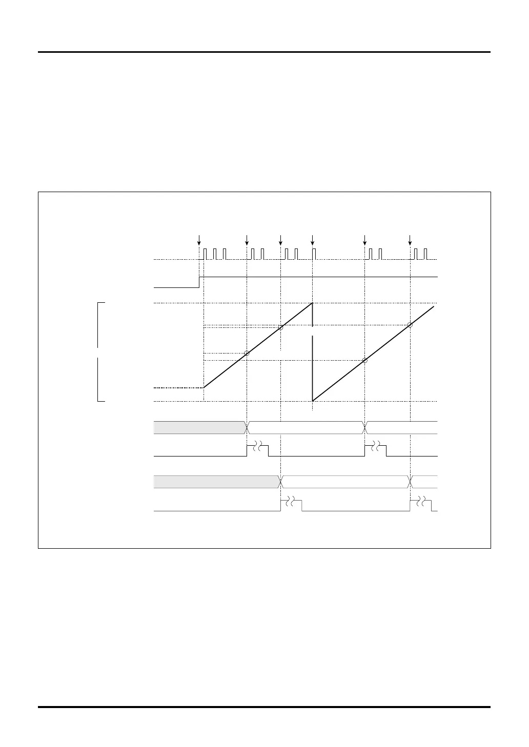
10.6.7 Operation of TML Measure Input
(1) Outline of TML measure input
In TML measure input, when the reset input signal is deasserted, the counter starts counting up synchro-
nously with the count clock. Upon event input to measure registers 0–3, the counter value is latched into each
measure register.
A TIN interrupt request can be generated by measure signal input from an external device. However, no TML
counter overflow interrupts are available.
Figure 10.6.2 Typical Operation of TML Measure Input
Count clock
Counter (32-bit)
H'FFFF FFFF
H'0000 0000
Enabled
(by deassertion
of reset)
Undefined
Reset
Note: • This diagram does not show detailed timing information.
Measure 0 register
Overflow
occurs
TIN23 interrupt request
Measure 1 register
TIN22 interrupt request
Measure
event 0
occurs
H'8000 0000
H'C000 0000
H'8000 0000
H'6000 0000
H'6000 0000
H'D000 0000
Undefined
value
Undefined
H'C000 0000
H'D000 0000
Measure
event 0
occurs
Measure
event 0
occurs
Measure
event 0
occurs

 Loading...


