18
18-2
OSCILLATOR CIRCUIT
32180 Group User's Manual (Rev.1.0)
18.1 Oscillator Circuit
The M32R/ECU contains an oscillator circuit that supplies operating clocks for the CPU core, internal peripheral I/
O and internal memory. The frequency supplied to the clock input pin (XIN) is multiplied by 8 by an internal PLL
circuit to produce the CPU clock, which is the operating clock for the CPU core and internal memory. The frequency
of this clock is divided by 4 in the subsequent circuit to produce the peripheral clock, which is the operating clock
for the internal peripheral I/O and external data bus.
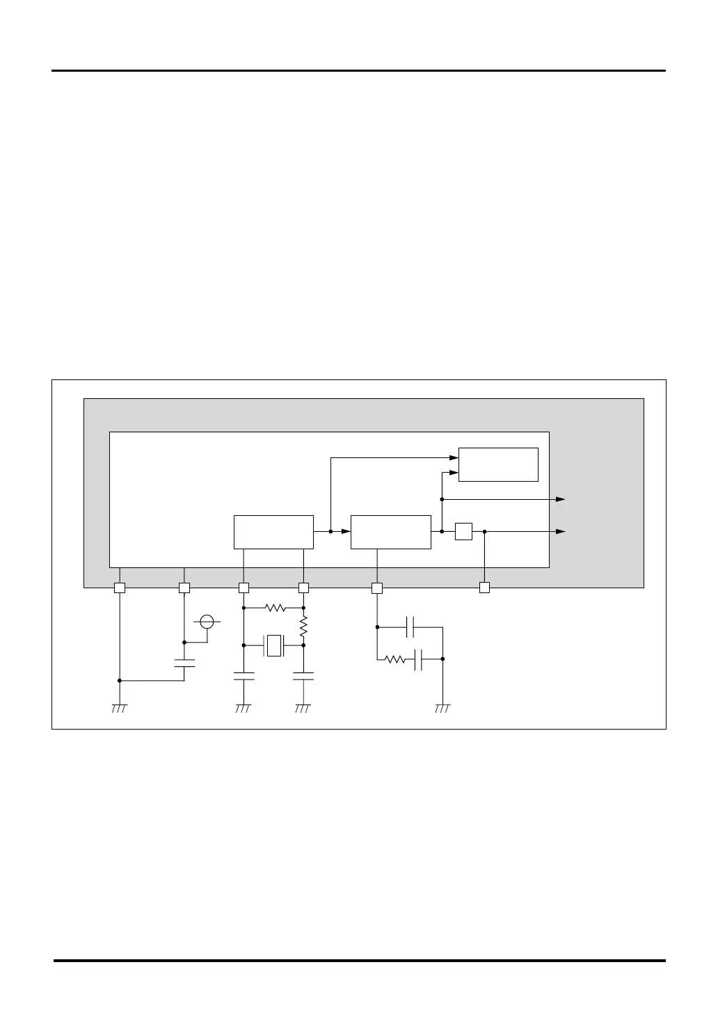
18.1.1 Example of an Oscillator Circuit
An oscillator circuit can be configured by connecting a ceramic (or crystal) resonator between the XIN and XOUT pins
external to the chip. Figure 18.1.1 shows an example of a system clock generating circuit using a resonator connected
external to the chip and an RC network connected to the PLL circuit control pin (VCNT). For the constants Rf, CIN,
COUT and Rd, the resonator manufacturer should be consulted to determine the appropriate values.
To use an externally sourced clock signal without using an internal oscillator circuit, connect the external clock
signal to the XIN pin and leave the XOUT pin open.
18.1 Oscillator Circuit
Figure 18.1.1 Example of an Oscillator Circuit
M32R/ECU
OSC-VCC
XIN
XOUT
OSC-VSS
Rf
Rd
C
IN
COUT
VCNT
BCLK/P70
C
Oscillator circuit
To the
peripheral clock
PLL circuit
560pF
0.1µF
1KΩ
Oscillator module
To the
CPU clock
1/4
(Note 1)
(Note 1)
(Note 1)
Note 1: Permissible error ±10%
Oscillation stoppage
detection circuit