12
12-40
Serial I/O
12.6 Transmit Operation in UART Mode
32180 Group User's Manual (Rev.1.0)
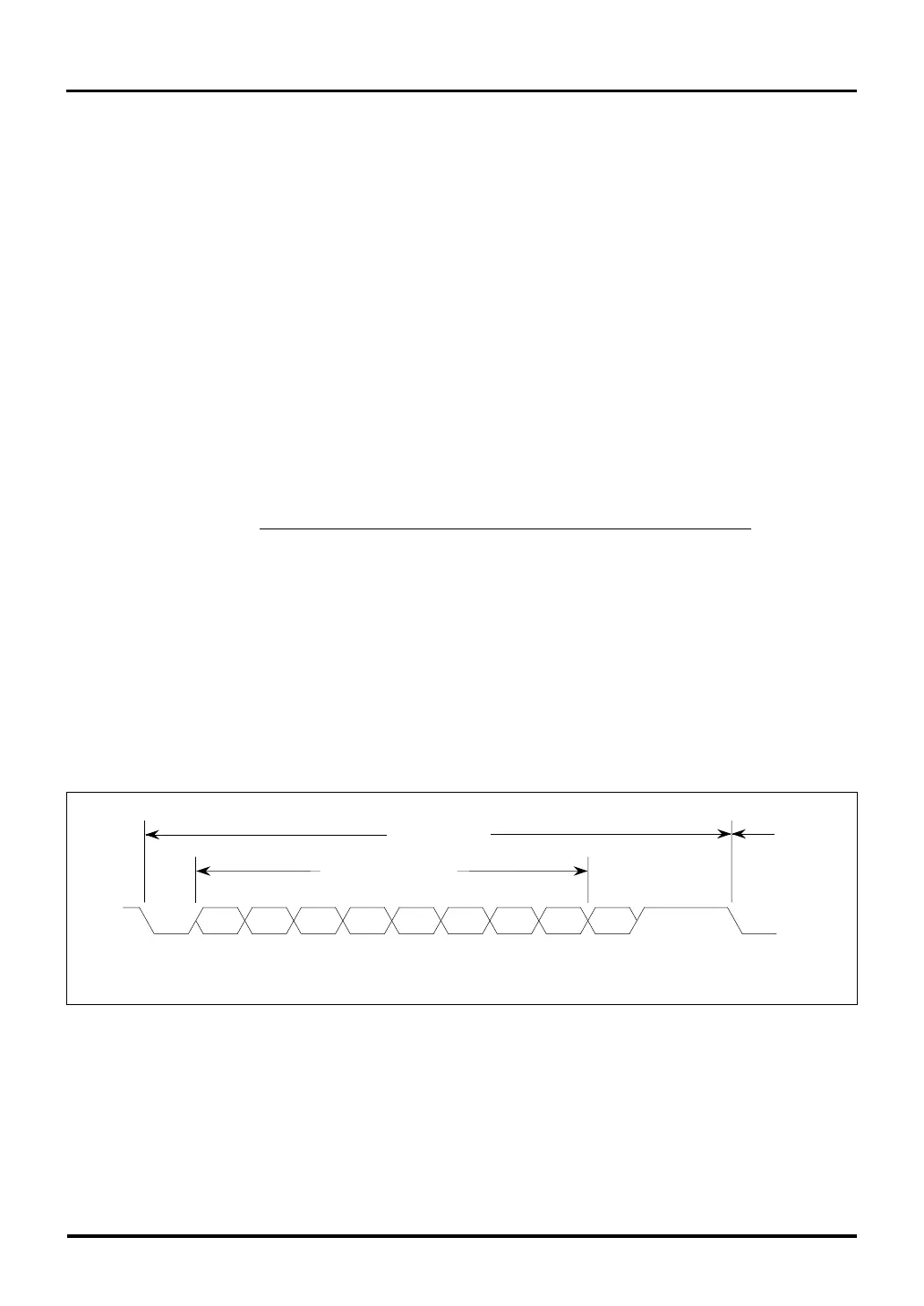
Figure 12.6.1 Example of a Transfer Data Format during UART Mode
ST b7 b6 b5 b4 b3 b2 b1 b0 PAR SP
SP
LSB MSB
ST
Parity
bit
Stop
bit
Start
bit
Data bits (8 bits)
Transmit data
Next
data
12.6 Transmit Operation in UART Mode
12.6.1 Setting the UART Baud Rate
The baud rate (data transfer rate) in UART mode is determined by a transmit/receive shift clock. During UART
mode, the source for this transmit/receive shift clock is always the internal clock no matter how the internal/
external clock select bit (SIO Transmit/Receive Mode Register bit 11) is set.
(1) Calculating the UART mode baud rate
After being divided by a clock divider, f(BCLK) is supplied to the Baud Rate Generator (BRG), after which it
is further divided by 16 to produce a transmit/receive shift clock.
The clock divider’s divide-by value is selected from 1, 8, 32 or 256 by using the SIO Transmit Control Regis-
ter CDIV (baud rate generator count source select) bits (bits 2–3).(Note 1)
The Baud Rate Generator divides the clock divider output by (baud rate register set value + 1) and further by
16, thus generating a transmit/receive shift clock.
When the internal clock is selected in UART mode, the baud rate is calculated using the equation below.
Baud rate =
f(BCLK)
[bps] Clock divider’s divide-by value x (baud rate register set value + 1) x 16
Baud rate register set value = H’00 to H’FF (Note 1)
Clock divider’s divide-by value = 1, 8, 32 or 256
Note 1: If divide-by-1 (i.e., f(BCLK) itself) is selected as the baud rate generator count source,
make sure the value set in the baud rate register is equal to or greater than 7.
12.6.2 UART Transmit/Receive Data Formats
The transmit/receive data format during UART mode is determined by setting the SIO Transmit/Receive Mode
Register. Shown below is the transmit/receive data format that can be used in UART mode.

 Loading...


