14
14-9
REAL TIME DEBUGGER (RTD)
14.3 Functional Description of the RTD
32180 Group User’s Manual (Rev.1.0)
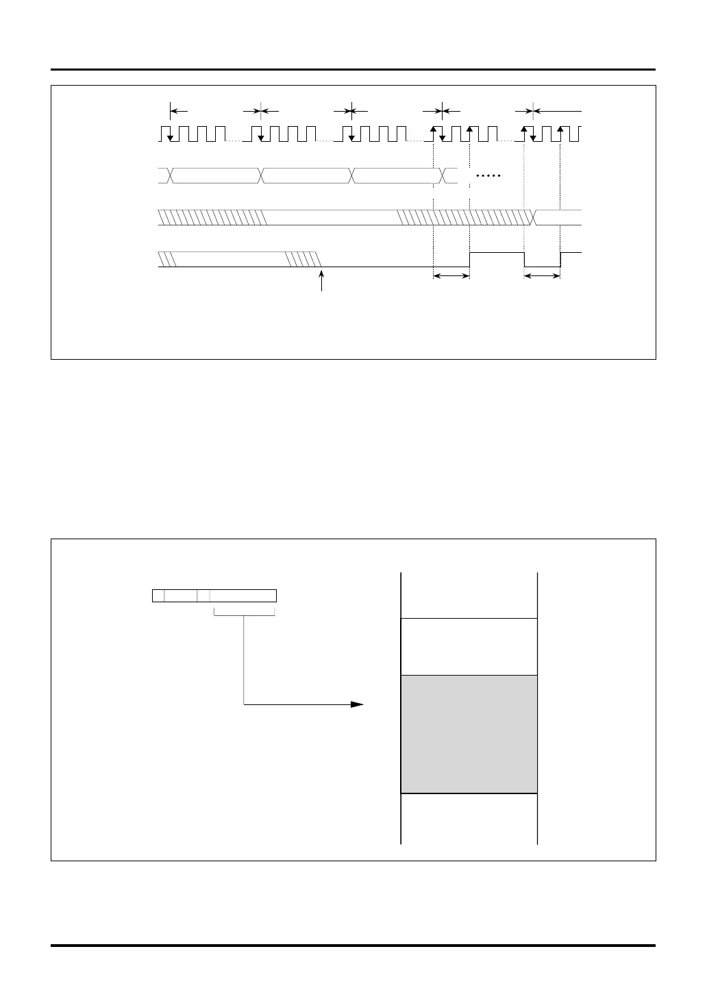
RCV
RCV command stored
RTDCLK
RTDRXD
RTDTXD
RTDACK
RCV
Bits 20-31
D(A1)
Indeterminate data during runaway condition
Indeterminate value during runaway condition
Note: • The next command following the RCV command must have all of its bits 20-31 set to 1.
Next command following RCV command
2 clock periods
1
• • •
1 RDR(A1)
32 clock
periods
32 clock
periods
32 clock
periods
32 clock
periods
2 clock periods
Figure 14.3.11 Operation of the RCV Command
14.3.7 Method for Setting a Specified Address when Using the RTD
In the Real-Time Debugger (RTD), the low-order 16-bit addresses of the internal RAM can be specified. Be-
cause the internal RAM is located in a 48-KB area ranging from H’0080 4000 to H’0080 FFFF, the low-order 16-
bit addresses of that area (H’4000 to H’FFFF) can be set. However, it is inhibited to access any location other
than the area in which the RAM is located. Note also that two least significant address bits, A31 and A30, area
always 0 because data are read and written to and from the internal RAM in a fixed length of 32 bits.
SFR 16KB
H'0080 0000
H'0080 4000
Memory map
H'0080 FFFF
XXA29 – A16
Only H'0080 4000 to H'0080 FFFF
can be specified
• • •
RAM area
Figure 14.3.12 Setting Addresses in the Real-Time Debugger