TPS-1 User’s Manual: Hardware 1. Overview
R19UH0081ED0107 Rev. 1.07 page 10 of 86
Jul 30, 2018
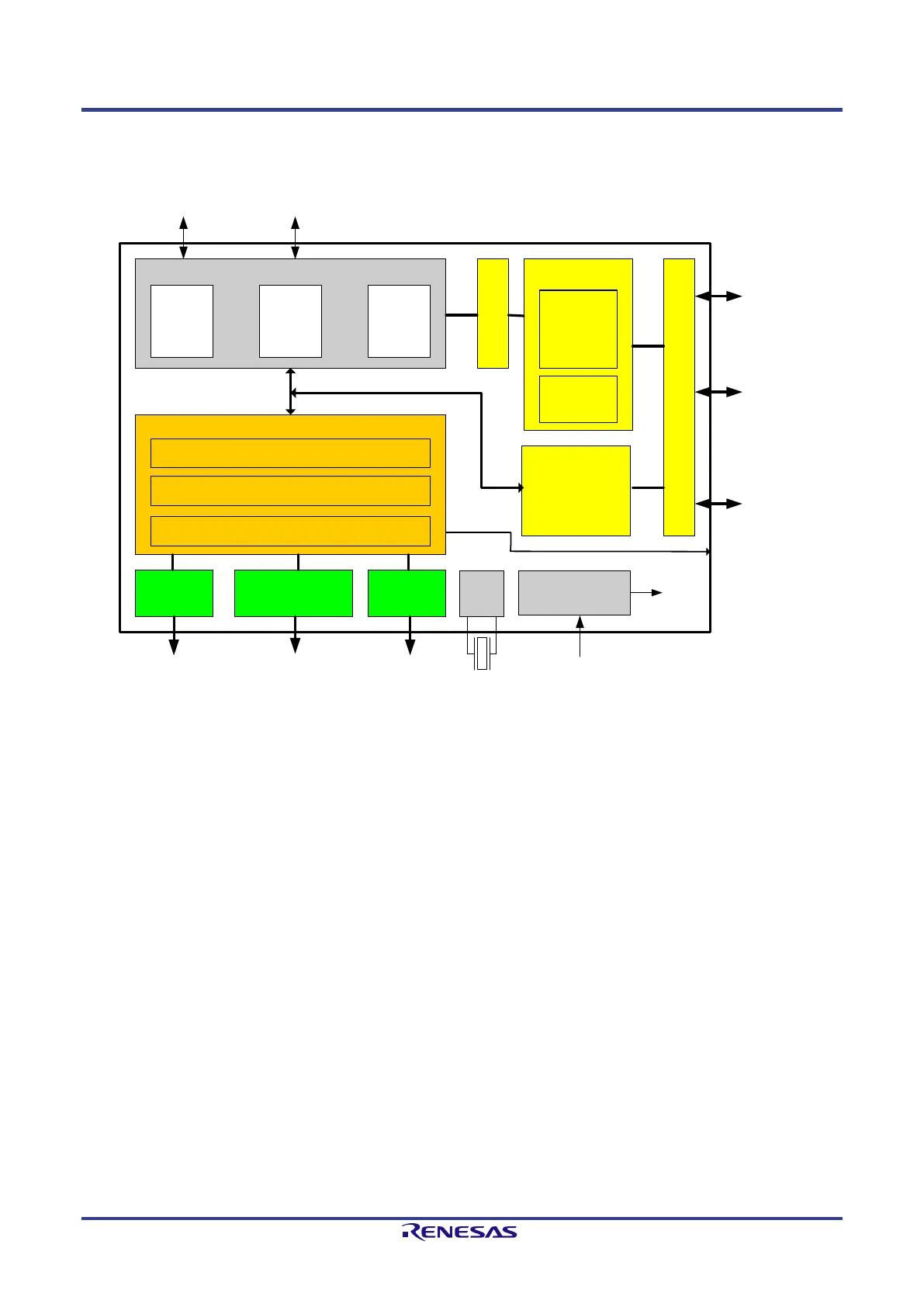
1.3. Block Diagram
The block diagram shows the internal structure and main components of the TPS-1.
The additional serial boot Flash component, the oscillator and the physical adaptation for the Ethernet interfaces are not listed.
Shared Memory
I/O Interface
PHY 2PHY 1
SPI
Slave
Parallel
Interface
8 / 16 Bit
Host Interface
M U X
PROFINET CPU
Boot-
ROM
ARM
Core
RAM
PROFINET Core
Time Sync
IRT Switch
Protocol Handling
LAN signals
(I2C-bus, link and
Activity), Test Sync
Clock Signals T1 to T6
Clock
Unit
25 MHz
MDI MDI
Link1, Act1, Link2, Act2
Test Sync
JTAG / Debug
Serial Flash
(SPI Slave)
Host Interface /
Parallel - Serial
48 GPIO
Status Info
LEDs
Control Signals
Power Supply
Switching Regulator
3.3 V
1.5 V
Figure 1-2: TPS-1 Block Diagram
The TPS-1 contains the PROFINET CPU, the PROFINET core, the I/O interface, and the Host Interface for connecting a host CPU.
The PROFINET core processes the PROFINET communication. All time-critical services are implemented in hardware to realize high performance.
The communication between an external host CPU and other PROFINET components is processed by the PROFINET CPU (connection establishment,
administration and management of Application Relations, controlling of Ethernet connections, setup and monitoring of RT and IRT channels, etc.).
Simple IO interfaces can be realized with the I/O interface only (e.g. digital I/Os)
 Loading...