TPS-1 User’s Manual: Hardware Appendix. B Board Design Information
R19UH0081ED0107 Rev. 1.07 page 82 of 86
Jul 30, 2018
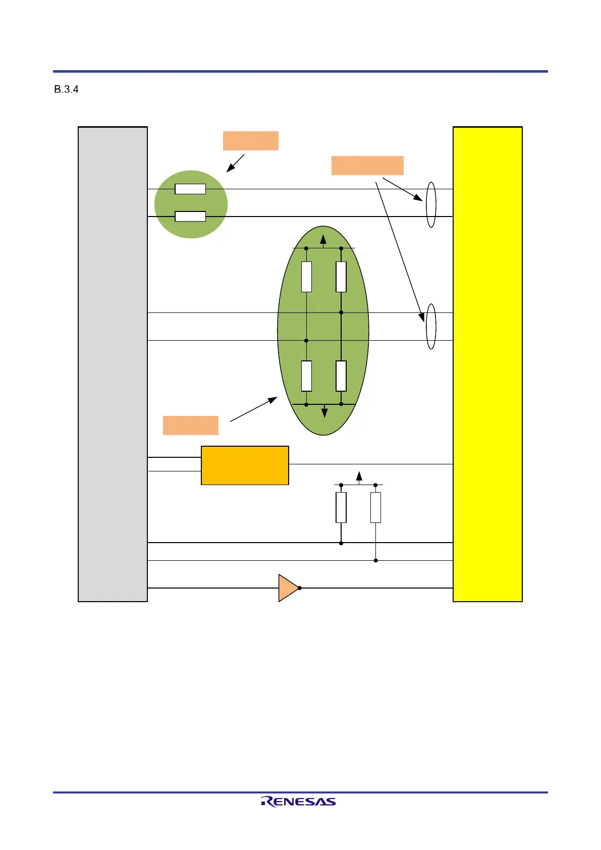
100BASE-FX Mode Circuitry
In case of 100BASE-FX operation, a PN-IO compliant optical transceiver module like Avago AFBR-5978Z or QFBR-5978Z is connected to the FX
interface. The signals between the PHY and the transceiver module are 100 Ω differential respectively 50 Ω single-ended signals.
TPS-1
R = 150 Ω
R = 150 Ω
PxTD_OUT_P
PxTD_OUT_N
Vcc 3.3V
GND
R = 130 Ω
R = 130 Ω
R = 82 Ω
R = 82 Ω
Place close to
TPS-1
Place close to
TPS-1
50 Ω impedance
PxRD_P
PxRD_N
SD-active circuitry
(See next Figure)
Px_SD_P
Px_SD_N
Vcc 3.3V
IC2_x_D_INOUT
SCLK_x_INOUT
R = 10 kΩ
R = 10 kΩ
Px_FX_EN_OUT
Transceiver
(AFBR-5978Z)
QFBR-5978AZ
Tdata+
Tdata-
Rdata+
Rdata-
SD
Sda
Scl
Txdis
Figure B-8: 100BASE-FX Interface Example
Note: All resistors in this example should have a tolerance of 1%.
 Loading...