TPS-1 User’s Manual: Hardware 3. Host Interface
R19UH0081ED0107 Rev. 1.07 page 24 of 86
Jul 30, 2018
3.3. SPI Slave Interface
Another way to connect a host CPU is the SPI interface. The maximum speed for serial access to the shared memory is 25 MHz. The transmission clock
frequency should range between 1 MHz and 25 MHz. A control unit for processing the SPI Master commands is implemented into the TPS-1.
The SPI Master commands are described in this chapter.
Table 3-6: SPI host interface signals
Signal designation Function Remarks
P3 GPIO_38 HOST_RESET_IN Serial Reset The SPI Slave interface can
be reset by using this signal
(signal is active high).
transfer is signalized.
N2 GPIO_40 HOST_SRXD_IN Serial Data Input MOSI (Master out Slave in)
Serial Clock driven by the
SPI Master
M4 GPIO_42 HOST_STXD_OUT Serial Data Output MISO (Master in Slave out)
Serial Header Information
header information available
An unknown or wrong SPI access causes an „Error-IRQ“ that is reported to the host CPU by the event unit.
The clock phase and the CPOL (clock polarity) is adjustable (active low, active high).
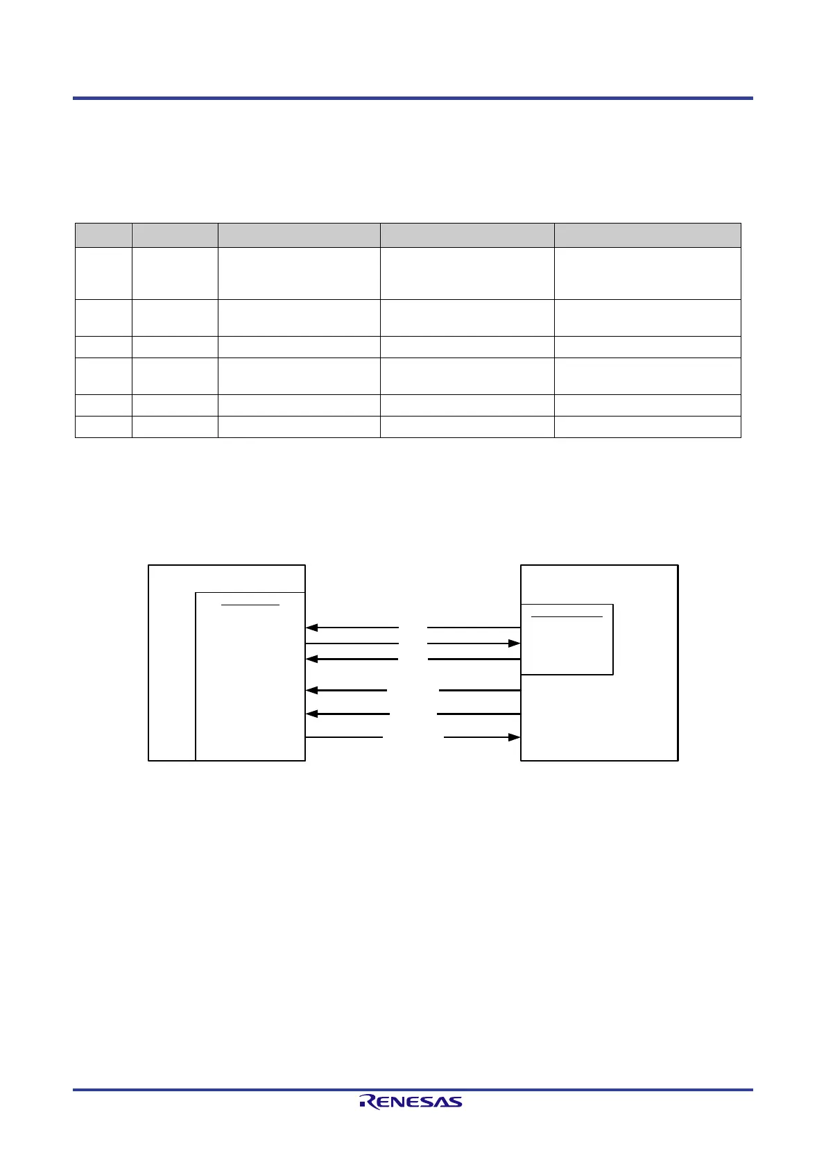
The following figure shows the connection of a host CPU (V850ES/JG2) to the SPI Slave interface of the TPS-1. The “chip select” line is not
connected. The data transfer is controlled by the status of the “clock line” (CSI-Master).
The pins HOST_RESET_IN, HOST_SFRN_IN and HOST_SHDR_OUT are not supported directly by the HOST-CPU. They have to be simulated by
the pins P02, P03 and P04.
TPS-1
SPI-SLAVE
HOST-CPU
(V850ES/JG2)
MOSI
MISO
SCLK
CSIBx-Master
SOBx
SIBx
SCKBx
HOST_STXD_OUT
HOST_SRXD_IN
HOST_SCLK_IN
SPI-Reset
SFRN_IN
SHDR_OUT
HOST_RESET_IN
HOST_SFRN_IN
HOST_SHDR_OUT
P02 (Output)
P03 (Output)
P04 (Input)
Figure 3-8: Connection of a V850 CPU to the SPI interface