TPS-1 User’s Manual: Hardware Appendix. B Board Design Information
R19UH0081ED0107 Rev. 1.07 page 80 of 86
Jul 30, 2018
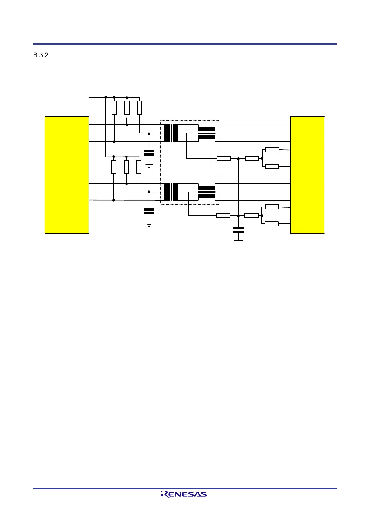
100BASE-TX Mode Circuitry
The analog input and output signals are very noise-sensitive and the PCB layout of these signals should be done very carefully. Transmit and receive
lines must be routed with differential 100 Ω impedance and the trace length must be kept as short as possible.
The EXTRES input must be connected to analog GND with a 12.4 kΩ resistor (1% tolerance). See “Additional TPS-1 Pins”.
The figure below shows a typical circuit example for a 100BASE-TX operation mode.
RJ45
TPS-1
75 Ω
50 Ω
50 Ω
50 Ω
75 Ω
50 Ω
50 Ω
50 Ω
50 Ω
50 Ω
10 Ω
50 Ω
50 Ω
10 Ω
Analog 3.3 V
(PHY)
P(2:1)_TX_P
P(2:1)_TX_N
P(2:1)_RX_P
P(2:1)_RX_N
AGND (PHY)
AGND (PHY)
Case GND or
digital GND
10 nF / 2 kV
10 nF
10 nF
1
2
3
4
5
6
7
8
*
*
*
*
Unmarked resitors: 1/16 W and 1% tolerance
Resitors marked with „*“: 1/8 W and 1% tolerance
Figure B-6: 100BASE-TX Interface circuit Example
 Loading...