Installation: G3 Interface Unit Type 9001 (D418-06)
D418 22 SM
Line Connection and Settings
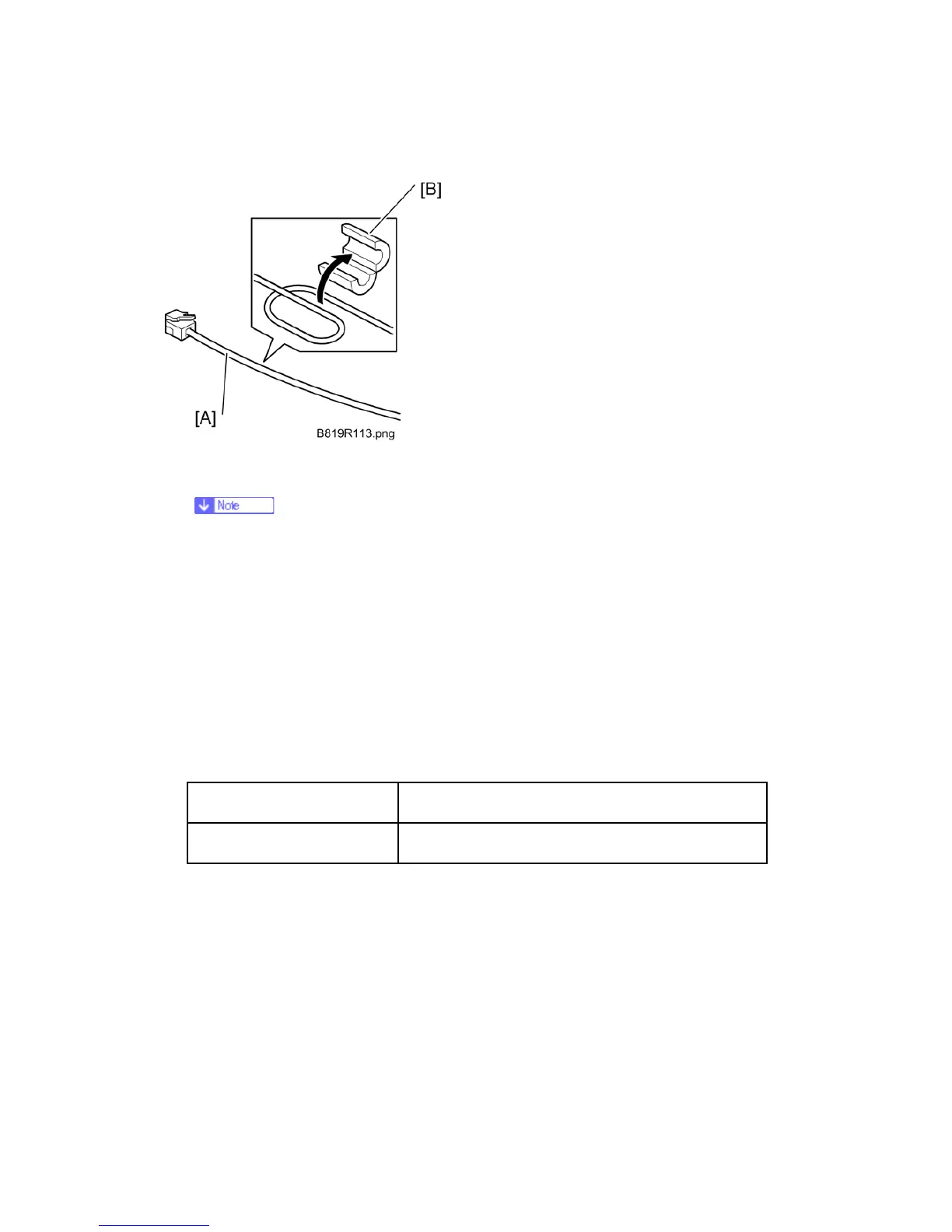
1. Loop one end of the telephone cable [A] once, then enclose it with the ferrite core
(RFC-9) [B] as shown.
Attach the ferrite core at least 9 cm (3.5 in.) from the connector.
Attach a ferrite core to the 2nd G3 line if two G3 boards are installed.
2. Connect the telephone cable to "LINE 2" jack.
-or-
If two G3 boards are installed, connect the cables to "LINE 2" and "LINE 3" jacks.
3. Connect the machine power cord to the power supply, then turn on the main power
switch.
4. Enter the Service Mode.
5. Touch "Fax SP"
6. Do these communication switch settings:
SP1104-23 (Switch 16)
Set Bit 1 "1".
Set Bit 3 "1" if two G3 boards are installed.
7. Exit the Service Mode and turn the machine off/on with the main power switch.
8. Do SP5990-001 to print the system parameter list, then confirm that "G3" is listed as
an option.
9. Enter the Service Mode and set the items required for PSTN communication.
If one G3 line is installed, use SP3103 (PSTN-1 Port Settings) to do the PSTN
settings.
If two G3 lines are installed, use SP3103 (PSTN-1 Port Settings) and SP3104
(PSTN-2 Port Settings) to do the PSTN settings for the first and second G3 line.
 Loading...


