Home
Ricoh
All in One Printer
Nashuatec CP430
Ricoh Nashuatec CP430 User Manual
4
of 1
of 1 rating
152 pages
Give review
Manual
Specs
To Next Page
To Next Page
To Previous Page
To Previous Page
Loading...
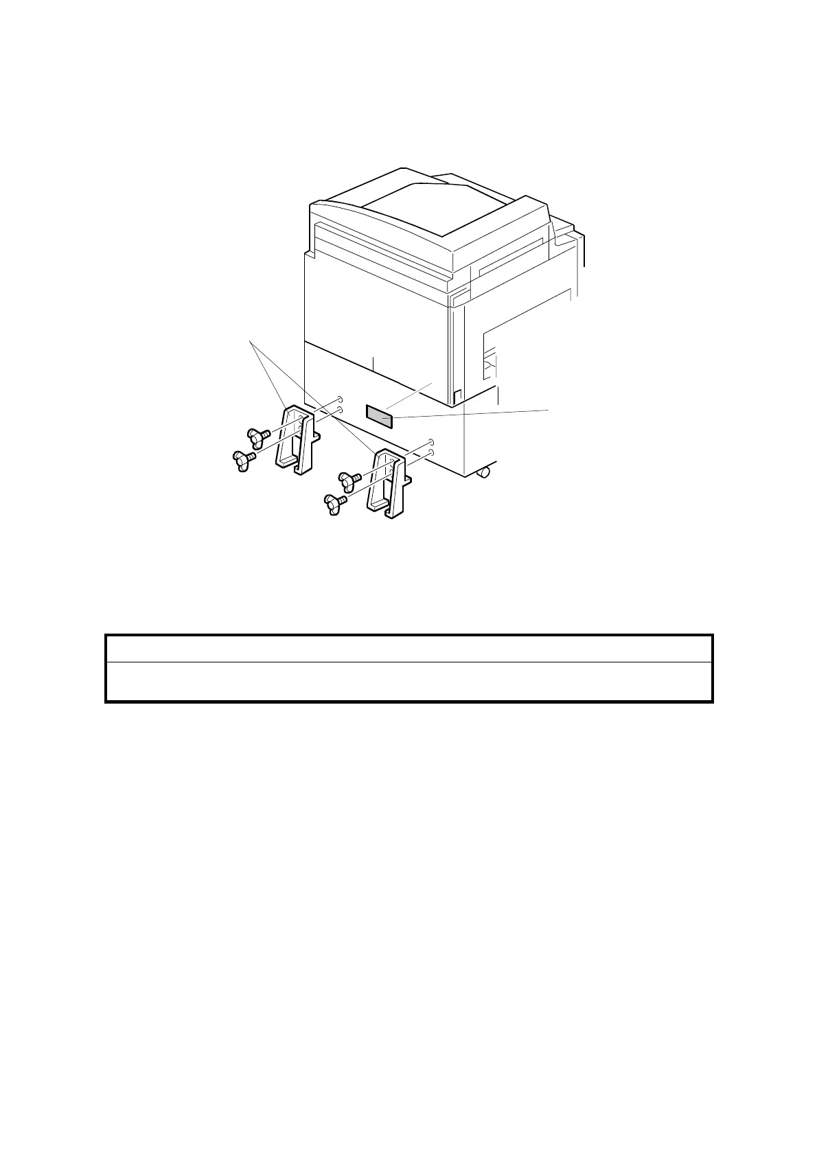
INSTALLATION PROCEDURE
31 October 2001
1-14
ADF stabilizer installatio
n
1.
Attach the two stab
ilizer brackets [A] to the back of the table using the
thumbscrews (4 screw
s).
2.
Attach the ca
ution label [B],
as show
n.
!
CAUTION
This procedure must be done to prev
ent the machine from falling
backwards when t
he ADF is open.
C238I040.
W
MF
[A]
[B]
23
25
Table of Contents
Default Chapter
4
Table of Contents
4
1 Installation
11
Installation Requirements
11
Optimum Environmental Condition
11
Environments to Avoid
11
Power Connection
11
Access to the Machine
12
Installation Procedure
13
Main Body
13
Accessory Check
13
Installation Procedure
16
Platen Cover Installation (Option)
19
Accessory Check
19
Installation Procedure
19
Adf Installation (Option)
20
Accessory Check
20
Installation Procedure
21
ADF Stabilizer Installation
24
Tape Marker (Option)
25
Accessory Check
25
Installation Procedure
26
For C238
26
For C231 and C237
27
For C226
28
For C210, C218, C219, C222, and C223
29
For C217 and C225
30
Common Steps
31
Additional Drums (Option)
32
Interface Board (Option)
33
Accessory Check
33
Installation Procedure
33
2 Preventive Maintenance
34
Maintenance Table
34
3 Replacement and Adjustment
36
General Caution
36
Covers / Boards
36
Front Cover / Panel
36
Rear Covers
37
Mpu
37
Psu
38
Scanner
39
Exposure Glass / Scales
39
Sbu and Lamp Stabilizer / Scanner Motor
39
Scanner H.p. Sensor / Platen Cover Sensor
40
Exposure Lamp (Xenon Lamp)
41
Scanner Wires
42
Installation
42
Image Adjustment
44
Master Eject
45
Master Eject Unit
45
Master Feed
46
Master Making Unit
46
Thermal Head
46
Installation
47
Thermal Head Voltage Adjustment
48
Master End Sensor Adjustment
49
Paper Feed
50
Pick-Up Roller / Paper Feed Roller / Friction Pad
50
Paper Separation Pressure Adjustment
50
Paper Width Detection Board
51
Printing
52
Press Roller
52
Press Roller Release Lever Adjustment
53
Printing Pressure Adjustment
54
Drum
55
Preparation
55
Cloth Screen
55
Installation
56
Clamper / Metal Screen
57
Installation
58
Ink Pump Adjustment
59
Ink Roller Unit / Ink Roller One-Way Clutch
61
Doctor Roller Gap Adjustment
62
Ink Detection Adjustment
63
Main Motor Pulley Position
63
Main Drive Timing Belt Adjustment
63
Paper Delivery
64
Paper Delivery Unit
64
Delivery Belt / Paper Exit Sensor
64
Exit Pawl Adjustment
65
Clearance Adjustment
65
Timing Adjustment
66
Air Pump Adjustment
67
Special Tools
68
4 Troubleshooting
69
Error Codes
69
Electrical Component Defects
71
Sensors
71
Switches
72
Lines
73
Fuse, Led, Vr, Dip-Sw, and Tp Tables
74
Blown Fuse Conditions
74
Led's
74
Vr's
74
Dip Switches
75
Test Points
75
5 Service Tables
76
Using Service Program Modes
76
Accessing Sp Modes
76
Entering SP Mode
76
Leaving SP Mode
76
How to Select a Program Number
77
Main Menu No.1: Copy Data
78
Sp Table
78
Sp1-70, 71: Firmware/Rom Suffix Information
79
Sp1-80: Error Code Information
79
Main Menu No.2: Basic Settings
80
Sp Table
80
Sp2-41, 2-42: Thermal Head Energy Control
80
Main Menu No.3: System Settings
81
Sp Table
81
Sp3-1: Input the Present Time
81
Main Menu No.4: Input Mode
82
Sp Table
82
Main Menu No.5: Output Mode
83
Sp Table
83
Main Menu No.6: Adjustment
84
Sp Table
84
Sp6-40: Ink Detection Adjustment
84
Image Adjustment (Sp6-10, -21, -5, -3, and -1)
85
SP6-10: Master Writing Speed
85
SP6-21: Paper Registration Position
85
SP6-05: Scanning Speed - Platen
86
SP6-06: Scanning Speed - ADF
86
SP6-03: Scanning Start Position - Platen
86
SP6-04: Scanning Start Position - ADF
86
SP6-01: Main Scan Position - Platen
86
SP6-02: Main Scan Position - ADF
86
Sp6-31: Sbu Calibration
87
Sp6-20: Registration Buckle (Not Used)
87
Main Menu No.7: Memory Clear
88
Sp Table
88
Sp7: How to Clear
88
Sp7-1: Factory Settings Clear
88
Main Menu No.8: System Test
89
Sp Table
89
Sp8-1: Download Main Firmware
89
Sp8-2: Upload Main Firmware
90
Sp8-10: Test Patterns
90
Sp8-21: Paper Feed Test (15 Rpm)
90
Sp8-22: Free Run Paper Feed (15 Rpm)
90
6 Detailed Section Descriptions
91
Mechanism Overview
91
Major Parts
91
Electrical Component Layout
92
Boards
93
Motors
93
Switches
94
Sensors
94
Solenoids
95
Counters
95
Others
95
Drive Layout
96
Master Eject Unit
97
Overview
97
Procedure
97
Master Clamper Opening Mechanism
98
Clamper Mechanism
98
Master Eject Roller Mechanism
99
Mechanism
99
Procedure
99
Pressure Plate Mechanism
100
Mechanism
100
Procedure
100
Scanner Unit
101
Overview
101
Scanner Drive
102
Full Size Mode
102
Reduction/Enlargement Modes
102
Image Processing
103
Overview
103
Auto Background Correction
104
Auto Shading
104
Mtf Filter
104
Main Scan Enlargement/Reduction
104
Binary Processing
105
Fine Mode
105
Thermal Head
106
Specifications
106
Thermal Head Control
106
Thermal Head Protection
106
Remarks for Handling the Thermal Head
107
Master Feed
108
Overview
108
Procedure
108
Master Feed Mechanism
109
Mechanism
109
Procedure
109
Clamper and Tension Roller Mechanism
110
Mechanism
110
Cutter Mechanism
111
Master Set Cover Sensor
111
Drum
112
Overview
112
Procedure
112
Drum Drive Mechanism
113
Mechanism
114
Ink Supply Mechanism
114
Mechanism
115
Ink Roller Mechanism
115
Mechanism
116
Ink Supply Control
116
Detection of Masters on the Drum
117
Paper Feed
118
Overview
118
Paper Feed Mechanism
119
Mechanism
119
Paper Feed / Separation Pressure Mechanism
120
Registration Roller Mechanism
121
Registration Roller Drive
121
Registration Roller Up/Down Mechanism
121
Printing Pressure Mechanism
122
Re-Feeding Mechanism
122
Paper Table Mechanism
123
Mechanism
123
Paper End Detection
123
Paper Size Detection
123
Side Fence Friction Pads
124
Paper Delivery
125
Overview
125
Paper Delivery Unit Drive Mechanism
125
Mechanism
125
Paper Separation from the Drum
126
Air Knife
126
Exit Pawl Air Pump
126
Exit Pawl Drive Mechanism
127
Timing Chart
128
Master Eject / Master Feed
128
Master Wrapping
130
Printing
132
Jam Detection
134
Master Eject Jam (E Jam Location Indicator)
134
Picking up the Used Master from the Drum
134
Just after Turning on the Main Switch
134
Df Jam (P Jam Location Indicator)
135
Feeding in the Original
135
Feeding out the Original
135
Turning on the Main Switch/Closing the DF Cover
135
Master Feed Jam (D Jam Location Indicator)
136
Cutting the Master (Master Not Cut)
136
Cutting the Master (Cutter Unit Problem)
136
Clamping the Master
137
Drum Jam (B Jam Location Indicator)
137
Wrapping Jam
137
Paper Feed Jam (a Jam Location Indicator)
138
Paper Feed
138
Turning on the Main Switch/End of Paper Feed
138
Paper Delivery Jam (C Jam Location Indicator)
138
Paper Delivery
138
7 Point to Point Diagram
139
4
Based on 1 rating
Ask a question
Give review
Questions and Answers:
Need help?
Do you have a question about the Ricoh Nashuatec CP430 and is the answer not in the manual?
Ask a question
Ricoh Nashuatec CP430 Specifications
General
Brand
Ricoh
Model
Nashuatec CP430
Category
All in One Printer
Language
English
Related product manuals
Ricoh MP C3004
2154 pages
Ricoh Pro 8300S
188 pages
Ricoh Aficio 1515
68 pages
Ricoh Aficio 3030
176 pages
Ricoh Aficio MP 4001
81 pages
Ricoh Aficio MP C2050
328 pages
Ricoh Aficio MP C2000
236 pages
Ricoh Aficio MP C2800
260 pages
Ricoh Aficio MP C3500
236 pages
Ricoh Aficio SP 3400SF
362 pages
Ricoh Aficio SP 100SU e
76 pages
Ricoh Aficio MP C2500 Series
6 pages
 Loading...