31 October 2001 SCANNER
3-7
Replacement
Adjustment
3.3.5 SCANNER WIRES
• Move the first scanner next to the opening in the frame.
• Exposure glass (☛ 3.3.1)
• SBU cover (☛ 3.3.2)
• Left stay (☛ 3.3.3)
• Rear and front frames (☛ 3.3.4)
1. First scanner ([1]: 2 pins)
NOTE: The drawings show only the front side. Repeat to remove components
on the other side.
[A]: Wire tension brackets (2 springs, ! x 2)
[B]: Scanner drive pulleys (2 Allen screws)
[C]: Scanner wires
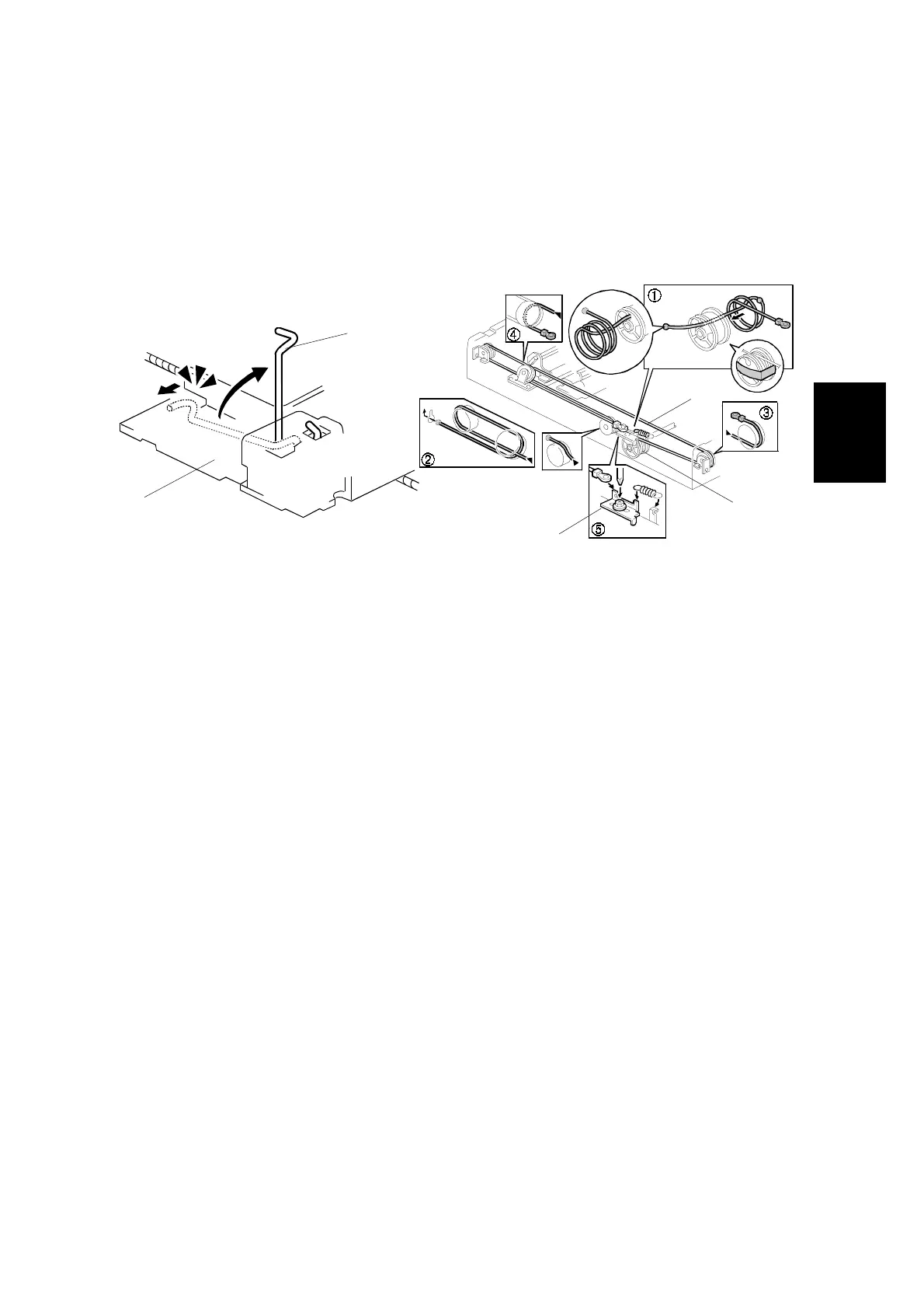
Installation
1. Wrap the new scanner wire around the pulley as shown
➀
, then temporarily
secure the pulley with tape.
2. Re-install the first scanner. Then secure the first and second scanner with the
scanner positioning pins (P/N A0069104), as shown in the illustration on the
next page.
3. Wind the new scanner wire around the scanner drive pulley in the correct way,
as shown.
4. Wind the end of the new wire with the ball as shown (
➁
).
5. Wind the end of the new wire with the ring as shown (
➂
,
➃
, and
➄
).
6. Connect the tension spring to the wire tension bracket (
➄
).
7. Wind the new scanner wire for the other side as well.
C238R046.WMF
C238R029.WMF
[B]
[C]
[D]
[A]
[1]
 Loading...