31 October 2001 MASTER FEED
3-13
Replacement
Adjustment
3.5.3 THERMAL HEAD VOLTAGE ADJUSTMENT
!
CAUTION
This adjustment is always required when the thermal head or PSU has been
replaced.
Purpose: To maintain master making quality and extend the lifetime of the thermal
head.
Standard: Refer to the voltage value (X) printed on the thermal head. The value
varies from one thermal head to another.
The adjustment voltage should be between X and X - 0.1 V.
Tools: Circuit tester
• Upper left cover (☛ 3.2.2)
• Read the voltage value on the
decal on the thermal head.
1. Slide out the master making unit.
CAUTION: Never turn VR1
clockwise rapidly
while the master
making unit is
connected. The T/H
will be damaged if too
much voltage is
supplied suddenly.
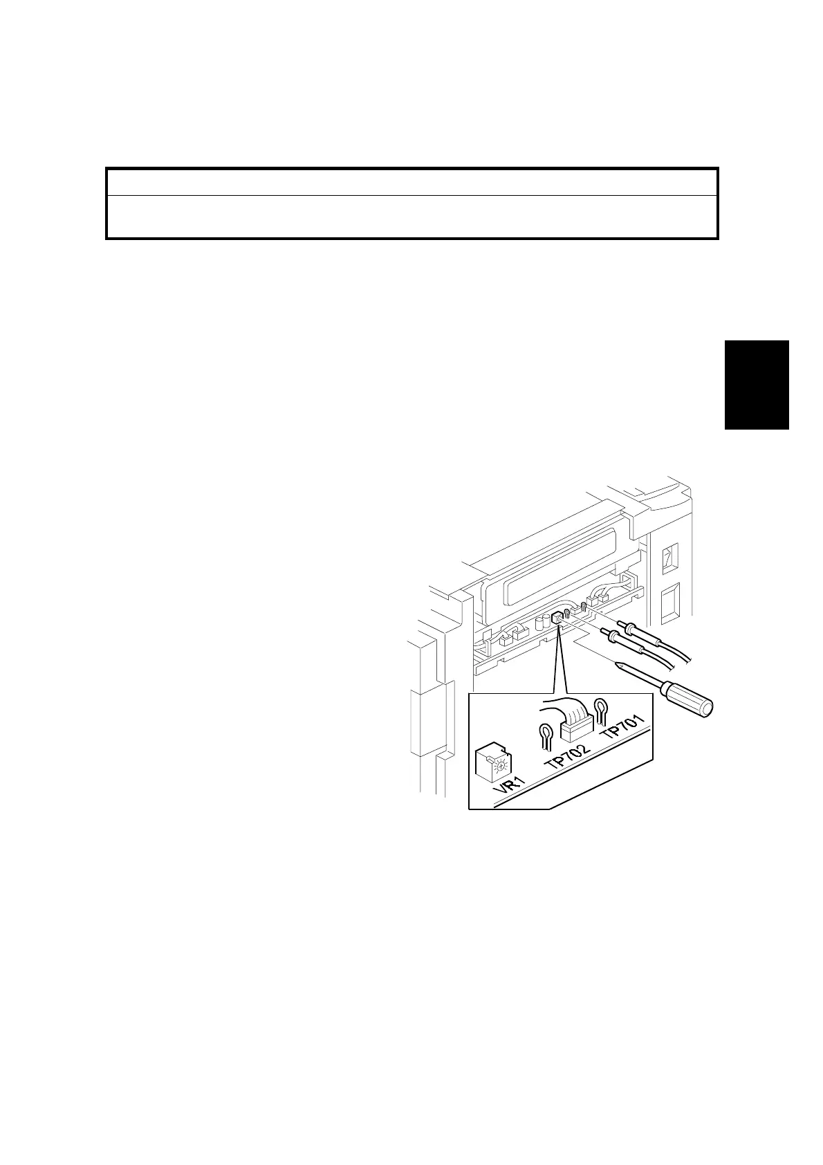
2. Connect the positive terminal of a
circuit tester to TP701 and the
negative terminal to TP702 .
CAUTION: If the output and
ground terminals
touch each other, the board will be damaged.
3. Connect the power plug, and turn on the main switch to access SP mode.
4. Select SP5-12 (Thermal head signal output).
5. Press the Start key. Power is continuously supplied to the thermal head, so
press the Stop key if you cannot finish the adjustment quickly.
A beeper sounds while the power is being supplied.
6. Measure the voltage, and turn VR1 so that the value becomes between “+0”
and “-0.1” volts from the value on the thermal head decal.
C238R012.WMF
 Loading...