A-2 Specifications
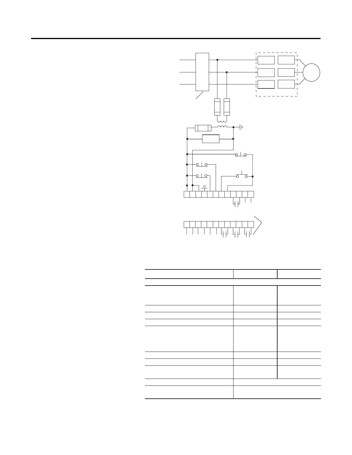
Wiring Diagram Figure A.1 Wiring Diagram
➀ Customer supplied.
Electrical Ratings
23 24 25 26
27
28 29 30 31 32 33 34
11 12 13 14
15
16 17 18 19 20 21 22
Option Input #1
Option Input #2
Stop
Start
SMC-Flex
Control Terminals
Normal/Up-to-Speed/External Bypass
Internal
Auxillary
Contacts
}
}
}
3-Phase
Input Power
Branch
Protection
SMC-Flex Controller
PTC
Input
TA C H
Input
Ground
Fault
Fault
Contact
Alarm
Contact
Aux #2
Normal
M
➀
➀
➀
➀
➀
➀
➀
➀
➀
➀
L1/1
T1/2
T2/4
T3/6
L2/3
L3/5
Fan
}
Not Used
Aux #1
UL/CSA/NEMA IEC
Power Circuit
Rated Operation Voltage 200…480V AC
200…600V AC
(–15%, +10%)
200…415V
200…500V
Rated Insulation Voltage N/A 500V
Rated Impulse Voltage N/A 6000V
Dielectric Withstand 2200V AC 2500V
Repetitive Peak Inverse Voltage Rating 200…480V AC:
1400V
200…600V AC:
1600V
200…415V: 1400V
200…500V: 1600V
Operating Frequency 50/60 Hz 50/60 Hz
Utilization Category MG 1 AC-53B:3.0-50:1750
Protection Against Electrical Shock N/A IP00 (open device)/
Optional IP20
DV/DT Protection RC Snubber Network
Transient Protection Metal Oxide Varistors:
220 Joules

 Loading...