Wiring 3-21
Soft Stop, Pump Control, and
SMB Smart Motor Braking
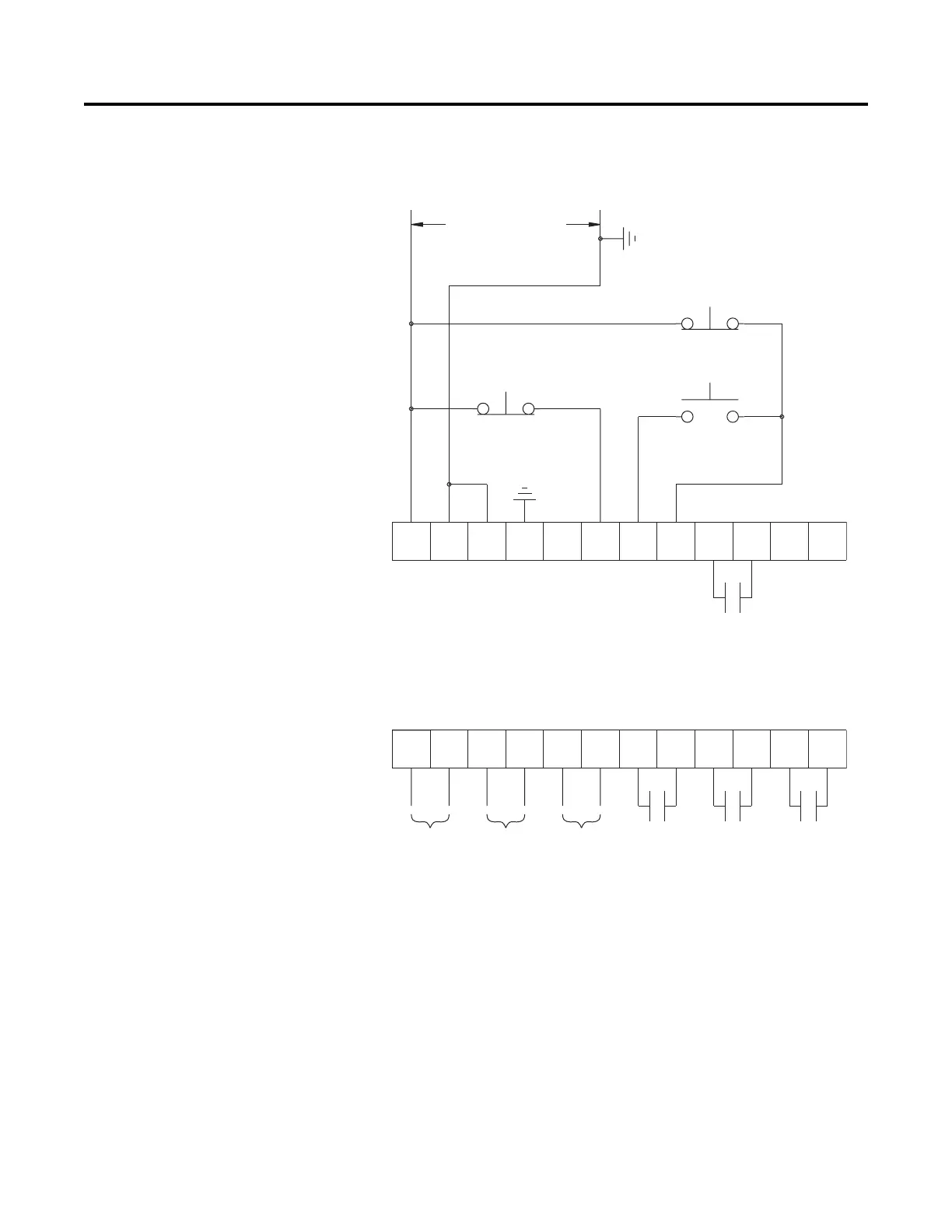
Figure 3.20 through Figure 3.23 show the different wiring for the Soft
Stop, Pump Control, and SMB Smart Motor Braking options.
Figure 3.20 Typical Wiring Diagram
➀
Customer supplied.
➁ Soft Stop, Pump Stop, or Brake.
➂ Refer to the controller nameplate to verify the rating of the control power input voltage.
Note: Refer to Chapter 3 for typical power circuits.
11 12
13
14
15 16
17
18 19 20
21
23
24
25 26
27
28 29
30 31 32 33
22
34
Option Stop
Stop
Start
Control Power
Alarm
Contact
Fault
Contact
Aux #2
Normal
Aux #1
Normal/Up-to-Speed/
Bypass
SMC-Flex
Control Terminals
PTC
Input
TACH
Input
Ground
Fault
➀
➀
➀➁
➂

 Loading...