Wiring 3-7
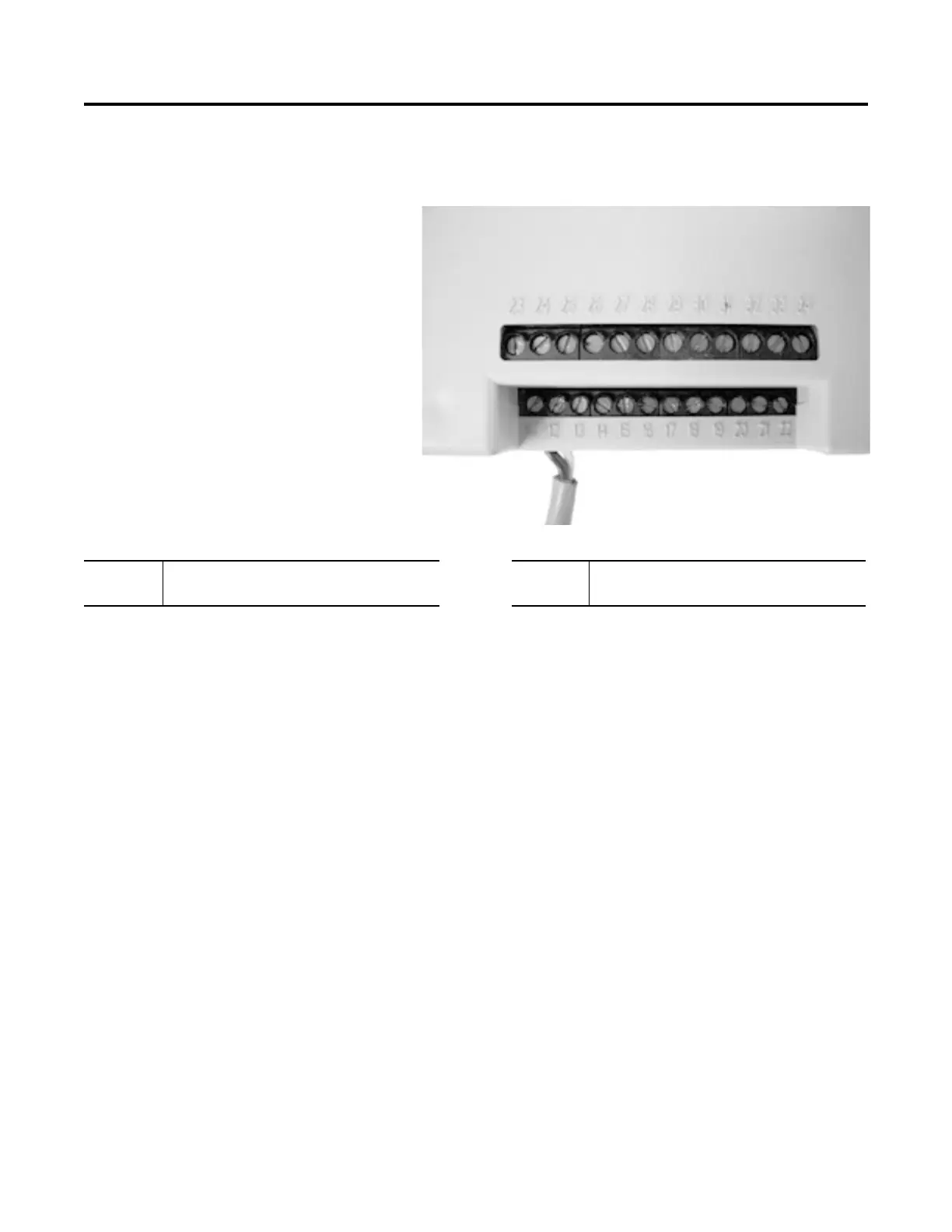
Control Terminal Designations As shown in Figure 3.6, the SMC-Flex controller contains 24 control
terminals on the front of the controller.
Figure 3.6 SMC-Flex Controller Control Terminals
➀
RC Snubbers are required on loads connected to auxiliary.
➁ Do not connect any additional loads to these terminals. These “parasitic” loads may cause problems
with operation, which may result in false starting and stopping.
➂ External Bypass operates an external contactor and overload relay once the motor reaches full
speed. The SMC-FLEX overload functionality, diagnostics and metering are disabled when the
external bypass is activated. Proper sizing of the contactor and overload is required.
Terminal
Number
Description
Terminal
Number
Description
11 Control Power Input ➀ 23 PTC Input ➁
12 Control Power Common ➀ 24 PTC Input ➁
13 Controller Enable Input ➁ 25 Tach Input
14 Control Module Ground 26 Tach Input
15 Option Input #2 ➀➁ 27 Ground Fault Transformer Input ➁
16 Option Input #1 ➀➁ 28 Ground Fault Transformer Input ➁
17 Start Input ➀➁ 29 Fault Contact (N.O./N.C.) ➀
18 Stop Input ➀➁ 30 Fault Contact (N.O./N.C.) ➀
19 N.O. Aux. Contact #1
(Normal/Up-to-Speed/External Bypass)
➀➂
31 Alarm Contact (N.O./N.C.) ➀
20 N.O. Aux. Contact #1
(Normal/Up-to-Speed/External Bypass)
➀➂
32 Alarm Contact (N.O./N.C.) ➀
21 Not Used 33 Aux Contact #2 Normal (N.O./N.C.) ➀
22 Not Used 34 Aux Contact #2 Normal (N.O./N.C.) ➀

 Loading...